In the last step (see Orient the C-Plane) we discussed different ways to orient the C-Plane. In this step we'll show you how to draw on a selected part face. This will come in handy if you want to identify your 3D parts or for modifying them. 1.First if you have completed and save the part model from Exercise #5 Connector Block, open that part now. It is shown below:
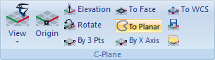
2.Now select the Modeling Aids
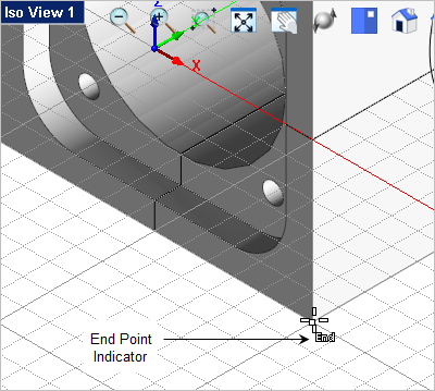
3.From the Modeling Aids 4.The first point selected will be the origin, so make sure the End Point Snap 5.Then select the bottom left corner end point of the right side face of the part. Note: Do Not pick until you see the "End" indicated at the cursor location.
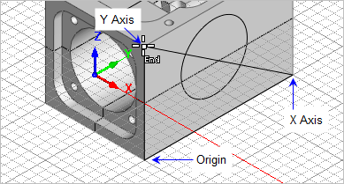
6.For the X Axis point select the end point at the back end of the part on the right side face. 7.For the Y Axis point select the end point at the top of the part on the right side face.
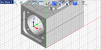
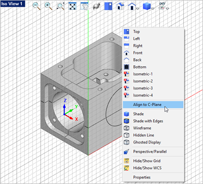
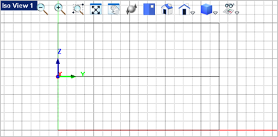
8.Now right-click anywhere in the view to display the Viewpoint pop-up menu and select the Align to C-Plane command. This menu contains the Viewport related commands.
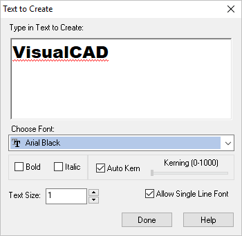
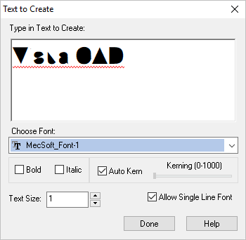
9.If you want to simply label your part you can add dimension text that will lie on the C-Plane. See Drawing & Dimensioning for that exercise. 10.In this exercise we will create text curves that you can engrave with the 2-1/2 Engraving toolpath strategy, go to the Curve Modeling 11.This will display the Text to Create dialog.
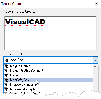
12.For engraving text you may want to use a single stroke font. From the Font drop-down menu select the text font named MecSoft_Font-1.
13.The text preview will now look like this.
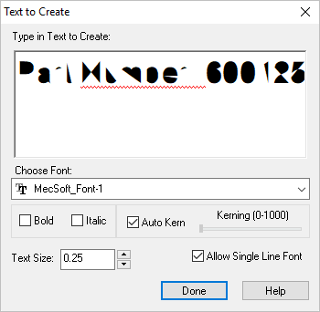
14.Make the following adjustments to the dialog: 15.Now place in the Type in Text to Create window, replace the text VisualCAD with the following text: 16.The dialog should look like this:
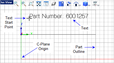
17.Now pick the Done button. The dialog will close and command prompt says: Enter start point of text. 18.You will see the text as you move the cursor around the Viewport. 19.Enable the Grid Snap
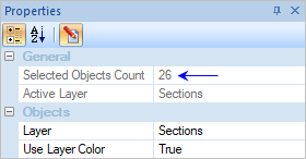
20.To select the curves, first make sure that the option Use Preselection Highlight is unchecked. It is located on the System section of the Options dialog (Home tab > Options > System). This was covered in the Set System Options section of Exercise #1. 21.Now select one of the curves in the text or window select all of the curves in the text and then pick the Properties 22.You will see that the text is actually 26 individual objects.
|