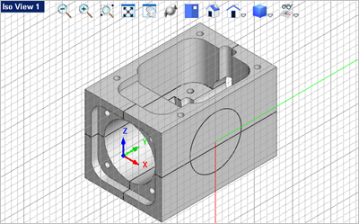
In this step we'll show you how to orient the Construction Plane (C-Plane). 1.First if you have completed and save the part model from Exercise #5 Connector Block, open that part now. It is shown below:
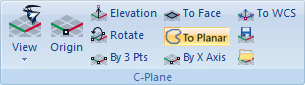
2.Now select the Modeling Aids tab. On the very right end of the ribbon bar you will find the C-Plane pane.
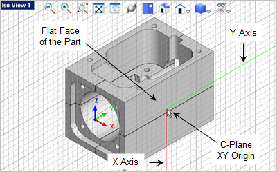
3.From the Modeling Aids 4.The command prompt says: "Pick a flat area". Select the right side face of the part and you will see that the C-Plane snaps to that face.
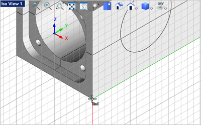
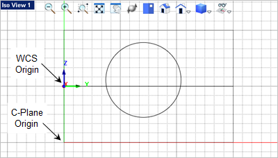
5.You can now see that the C-Plane and the Grid is alined with the right side flat face of the part. You will notice that the C-Plane origin is position at the point on the flat face you selected.
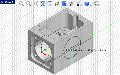
6.You can now draw on the C-Plane (see Text on a Part Face for more information). From the Curve Modeling 7.For the center point, toggle on the Grid Object Snap 8.Now select a point on the diameter of the circle.
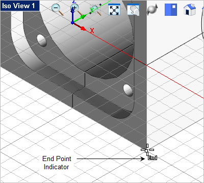
9.You can also move the C-Plane origin. From the Modeling Aids 10.The command prompt says: "Pick origin point or enter coordinates x,y and Z" Enable the End Point Snap
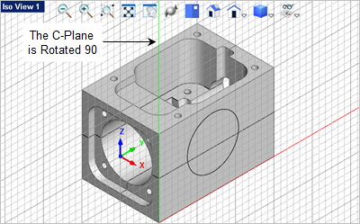
11.If you need the X Axis of the C-Plane aligned horizontally across the bottom of the part you can select the Rotate C-Plane about Axis 12.The command prompt says: "Enter axis to rotate about and angle to rotate by (eg: X,45)" We want to rotate the Z Axis 90 degrees so enter Z,90 in the command window
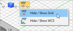
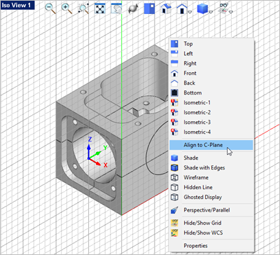
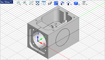
13.Now what if you want the view orientation aligned with the C-Plane? 14.Just right-click anywhere in the view to display the View pop-up menu and select the Align to C-Plane command. This menu contains many Viewport related commands.
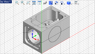
15.With the C-Plane aligned with the active Viewport pay close attention to where the origin of the C-Plane is:
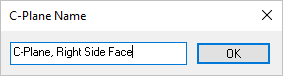
16.Now you may want to come back to the C-Plane later so let's save it. From the Modeling Aids 17.In the C-Plane Name dialog enter a unique name for the active C-Plane and then pick OK.
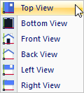
18.The active C-Plane is now saved with the part file. 19.Now let's change the C-Plane back to the default top view. From the Modeling Aids
20.Here is an easier way to align the C-Plane to the face AND align the XY Axis of the C-Plane at the same time. From the Modeling Aids 21.The first point selected will be the origin, so make sure the End Point Snap 22.Then select the bottom left corner end point of the right side face of the part. Note: Do Not pick until you see the "End" indicated at the cursor location.
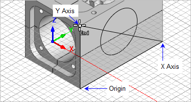
23.For the X Axis point select the end point at the back end of the part on the right side face. 24.For the Y Axis point select the end point at the top of the part on the right side face.
|