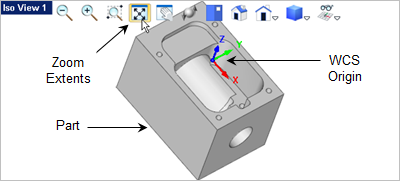
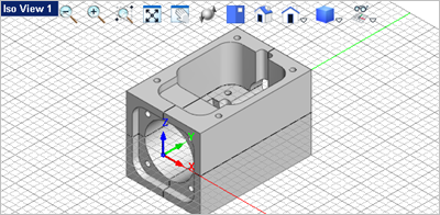
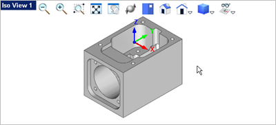
There may be times when you need to re-orient the part. This can happen at times when a part that you import into VisualCAD has it's WCS position skewed. In order to work with the part it has be oriented. We have deliberately skewed the part from Exercise #5 Connector Block so that it no longer lies parallel to any view. Here is what it looks like:
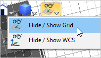
1.The first step toward to orienting this part is to define the C-Plane. For more about this see the topics Orient the C-Plane and Text on a Part Face in this exercise. 2.First make sure the Grid is visible. You can toggle the Grid on/off by selecting Hide / Show Grid from the View Toolbar.
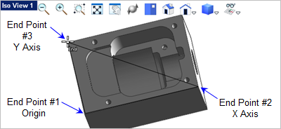
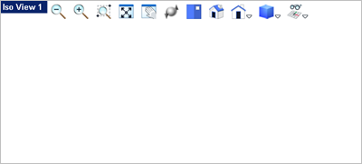
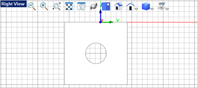
3.Now activate the view that allows you to see the planar face that you want to use to orient the part by. In this example it is Iso View 1 4.Go to the Modeling Aids 5.Activate the End Point Snap
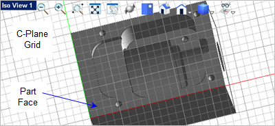
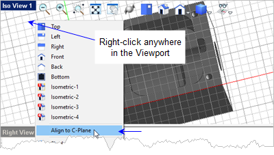
6.Now right-click anywhere in the Viewport (do not select any geometry) and select Align to C-Plane. This will align Iso View 1
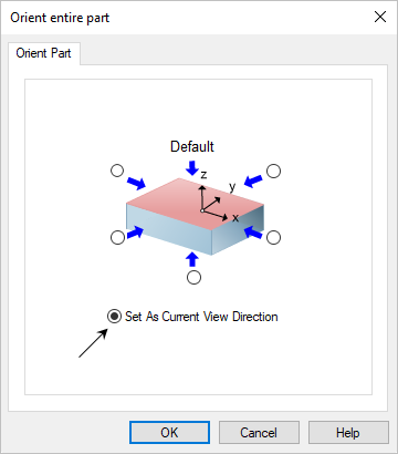
7.Now we can orient the part. Select the part and go to the Modify / Transform
8.This will display the Orient entire part dialog. Pick the option to Set as current view direction.
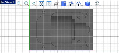
9.Pick OK and the part appears to disappear from the Viewport.
10.Now pick the Fit View
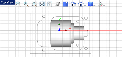
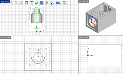
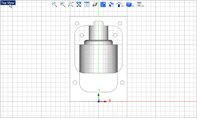
11.Now activate the Top View
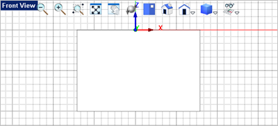
12.Repeat this for the Front View
13.Activate Iso View 1
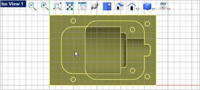
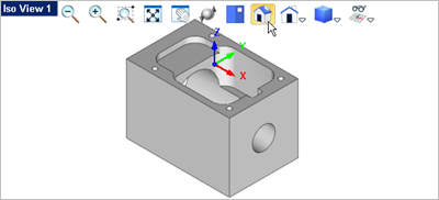
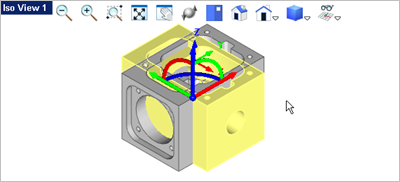
14.However, the part is still not oriented like the original part as shown below. You see that the length of the part was oriented along the Y Axis and the WCS was positioned at the center of the front view. Let's show you some additional commands to fix that.
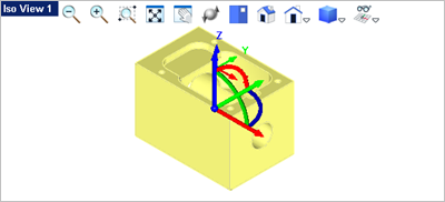
15.Activate Iso View 1 16.Now select the part to see the Graphic Manipulator displayed.
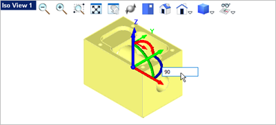
17.Pick the Z Rotation arc of the Graphic Manipulator
18.Now you see the part is rotated so press <Enter> to accept the rotation.
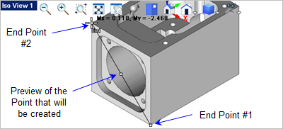
19.Zoom in on the front face of the part. 20.From the Curve Modeling 21.Activate the End Point Snap 22.Select the two diagonal end points on the front face of the part as shown.
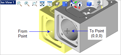
23.You can now toggle the Graphic Manipulator 24.With the point created, window select the entire part (and point) or simply press <Ctrl+A>. 25.From the Modify / Transform 26.The command prompt says: Pick from point or enter coordinates x,y and z. Make sure the End Point Snap
27.Now the command prompt says: Pick to point or enter coordinates x,y and z. In the command window enter 0,0,0
28.Now the part is aligned correctly accept for the C-Plane. Previously the C-Plane was aligned to the XY plane of WCS. 29.Activate the Top View
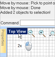
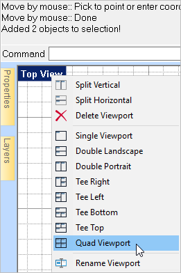
30.Now double-left-click on the Top View
31.Now right-click on the Top View
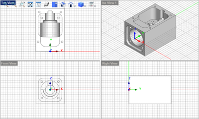
32.Save the file as Construction_Planes_Completed.vcp. Congratulations on completing this exercise! |