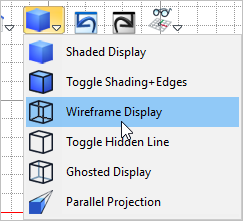
1.Activate the 2.Select the View
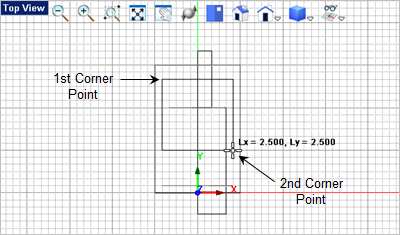
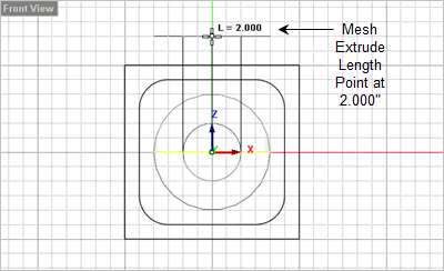
From the 3.For the first corner of the rectangle, select the upper right grid point location shown below or type 1.25,1.25,0 in the Command Prompt
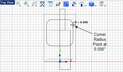
4.For the second corner of the rectangle, select the lower left grid point location shown below or type 1.25,1.5,0 in the Command Prompt 5.Now for the corner radius select the grid point shown below or enter 0.5 in the Command Window
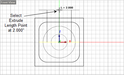
6.Now select the rounded rectangle you just created and from the 7.Move the cursor down to the Front View and select the Extrude Length at the 2.000 Grid point or enter 0,0,2 in the command window
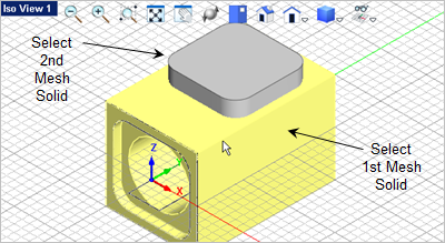
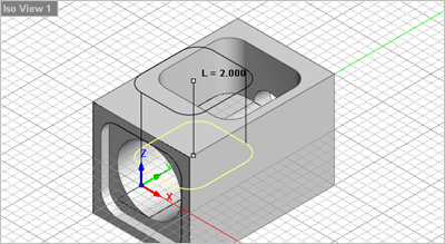
8.Now activate Iso View 1 and from the 9.For the first mesh solid select the Body.
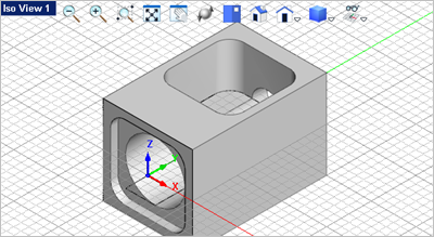
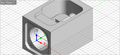
10.For the second mesh solid select the extrusion. The extrusion will be subtracted from the Body as shown below.
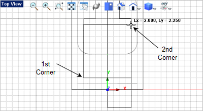
11.The top access has an additional pocket near the front of the body that needs to be modeled. 12.Activate the 13.From the 14.For the first corner of the rectangle, select the lower left grid point location shown below or type -1,0.5,0 in the Command Prompt
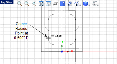
15.For the second corner of the rectangle, select the upper right grid point location shown above or type 1,2.75,0 in the Command Prompt 16.Now for the corner radius select the grid point shown below or enter 0.5 in the Command Window
17.Now select the rounded rectangle you just created and from the 18.Move the cursor down to the
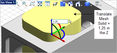
19.Now from 20.Click on the Blue Z Axis arrow and enter 1.25
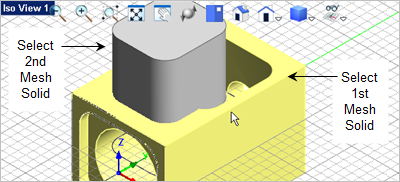
21.From the 22.For the first mesh solid select the Body. 23.For the second mesh solid select the extrusion you just created.
|