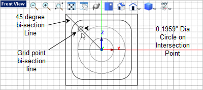
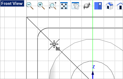
In this step we will model the tap drill mounting holes in the front and top access. Note: For machining purposes only a Point is required to perform a hole making operation. We are only modeling the holes here for learning purposes. 1.Activate the 2.To locate the center of the first hole you will draw two lines on the grid. From the Curve Modeling 3.Draw the two lines shown below. The first starts at the center and ends at the top left corner. The second passes diagonally across two grid points bisection the first line at 90 degrees. 4.Now from the Curve Modeling 5.For the circle center, activate the Intersect Object Snap
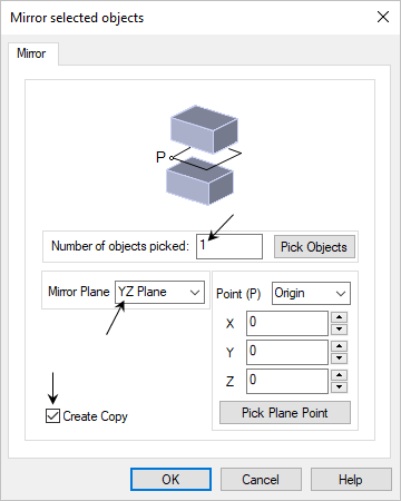
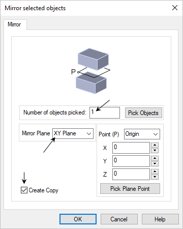
6.For the circle diameter enter 0.1959 in the Command Window 7.Now you need 4 of these holes. Let's use the mirror command to create the other three. First select the circle you just created, then go to the Modify / Transform 8.From the Mirror selected objects dialog, the Number of selected objects should be 1, The Mirror Plane should be YZ Plane and box next to Create Copy should be checked.
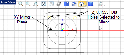
9.Pick OK from the dialog and the circle will be mirrored and both circles should be selected automatically. If not, select both of the circles and pick the
10.This time from the Mirror selected objects dialog, the Number of selected objects should be 2, The Mirror Plane should be XY Plane and box next to Create Copy should be checked.
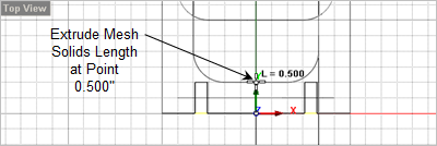
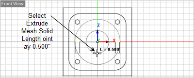
11.Now with all 4 circles drawn, all 4 should be selected automatically. If not select them now. 12.Now go to the 13.For the extrude length move the cursor to the
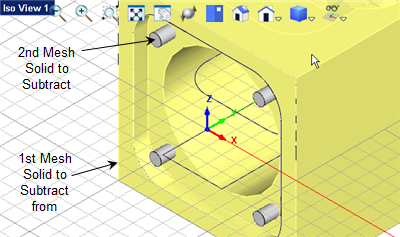
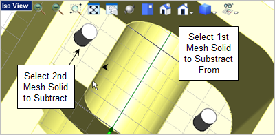
14.Now let's subtract the extrusions from the body to create the holes. Go to 15.For the first mesh solid select the body.
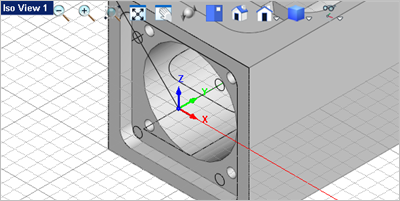
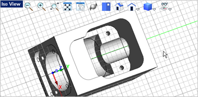
16.For the second mesh solid select one of the extrusions to subtract it. 17.Press the <Enter> key to repeat the command. This time select the body and then the second extrusion. 18.Repeat the command two more time until all 4 extrusions are subtracted from the body as shown below.
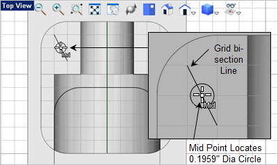
19.Now we have 2 additional holes of the same diameter located in the top access. Activate the 20.Let's change the display mode for the Top View. Select the Display menu from the View Toolbar in the Top View and select Toggle Shaded + Edges. 21.To locate the first hole, go to the Curve Modeling 22.Pick the two grid points shown below for the start and end points of the line. The line should bi-sect the two grid boxes from left to right as shown below.
23.Now from the Curve Modeling 24.From the Stats Bar activate the Mid Point Object Snap
25.For the center point of the circle select the mid point of the line you just created shown in the illustration above. 26.For the circle diameter enter 0.1959 in the Command Window 27.Now select the circle you just created and go to the
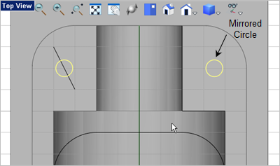
28.From the Mirror select objects dialog the Number of selected objects should be 1, the Mirror Plane should be YZ Plane and the Create Copy box should be checked. 29.Now pick OK to mirror the circle. 30.Both circles should now be selected. If not select them both now.
31.With the circles select go to the 32.From the Status Bar activate the Grid Object Snap 33.Move the cursor down to the
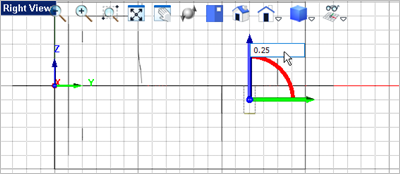
34.Now select the two extrusions and go to the 35.From the Graphic Manipulator, pick the Blue Z Axis arrow and then enter 0.25 in the input window and press <Enter>. The extrusions will translate up in the Z axis 0.25".
36.Now subtract them from the body. From the Curve Modeling 37.For the first mesh solid select the body. For the second mesh solid select one of the extrusions. 38.Press <Enter> to repeat the command and subtract the second extrusion from the body.
|