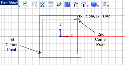
1.Activate the 2.From the tab 3.For the first corner of the rectangle, select the lower left grid point location shown below or type 1.25,1.25,0 in the Command Prompt
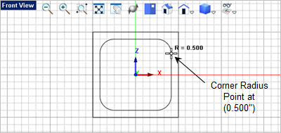
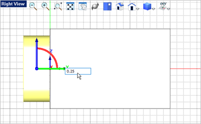
4.For the second corner of the rectangle, select the lower left grid point location shown below or type 1.25,1.25,0 in the Command Prompt 5.Now for the corner radius select the Grid point shown below or enter 0.5 in the Command Window
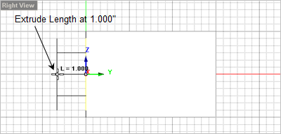
6.Now select the rounded rectangle you just created and from the 7.Move the cursor over to the
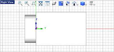
8.Now we will move the extrusion so that it intersects the body. Activate the Graphic Manipulator 9.Select the extrusion mesh solid to display the Graphic Manipulator 10.Pick the Green Y axis of the Graphic Manipulator
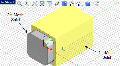
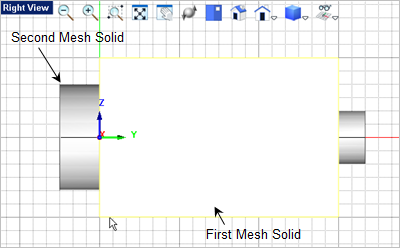
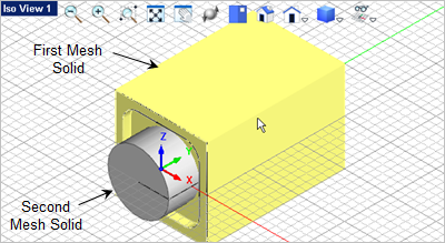
11.Press <Enter> again to accept the move. 12.Now activate the 13.For the first mesh solid select the Body.
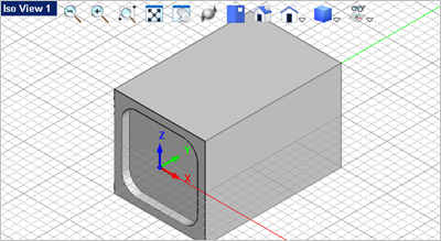
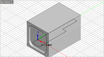
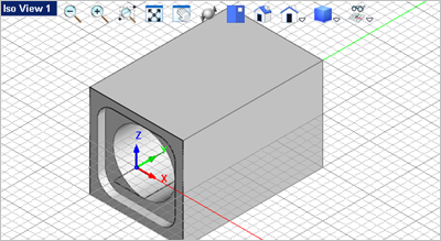
14.For the second mesh solid select the extrusion. The extrusion will be subtracted from the Body as shown below.
15.Now activate the Top View. 16.Select the View
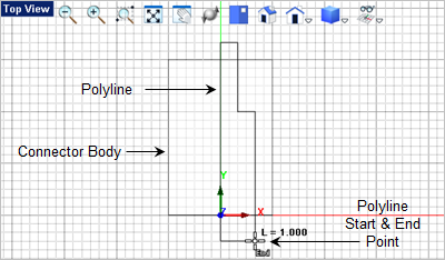
17.Now from the Curve Modeling 18.You will select the grid points shown below to define a closed polyline. The first grid point is the same as the last grid point.
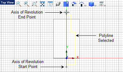
19.Now select the closed curve polyline you just created and from the 20.The command line
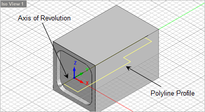
21.Now you want to subtract it from the Body. From the 22.For the first mesh solid select the Body. 23.For the second mesh solid select the Revolve.
|