1.Select the Curve Modeling tab 2.Now select the Rectangle command. 3.Turn on Grid snap
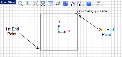
4.For the first corner of the rectangle, select the lower left grid point location shown below or type -1.5, 0, -1.5 in the Command Prompt 5.For the second corner of the rectangle, select the upper right grid point shown above or type 3,3 in the Command Prompt
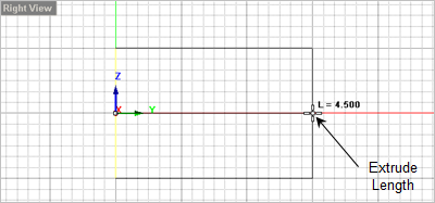
6.Now select the rectangle you just drew and then from the 7.Now drag the cursor over to the
|