| Extrude the Flange |
Now we will extrude the flange. 1.Activate the Top View
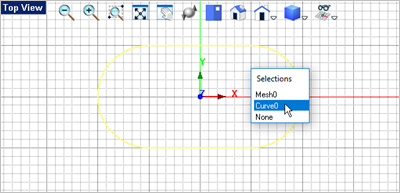
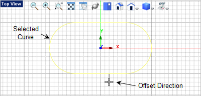
2.From the selection list pick Curve. The number value to the right of the curve may change depending on when the entity is created. 3.With the curve selected, from the Curve Modeling tab 4.If you move the cursor you see that an offset direction is indicated. Move the cursor below and on the outside of the curve as shown below.
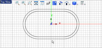
5.Most of the time in this exercise we are selecting grid points. The distance between each grid point is 0.25". For the offset distance you can select the next grid point below the curve.
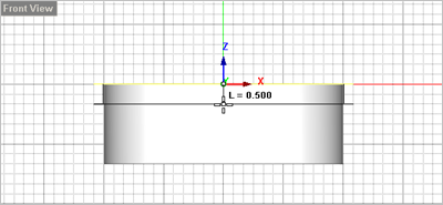
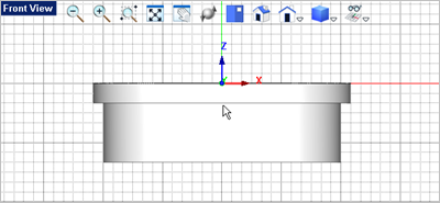
6.Now select the offset curve you just created, go to the Mesh Modeling tab 7.Drag the cursor to the Front View
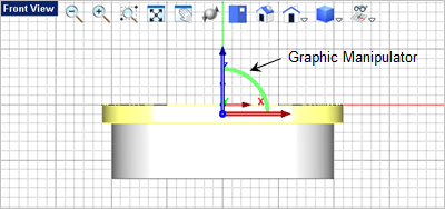
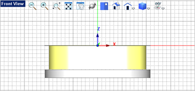
8.Now lets move the flange to the bottom of the body. To do this we will use the Graphic Manipulator. To toggle the Graphic Manipulator on, go to the Status Bar and select the icon 9.Now select the flange and you will see that the Graphic Manipulator is displayed on top of the selected entity.
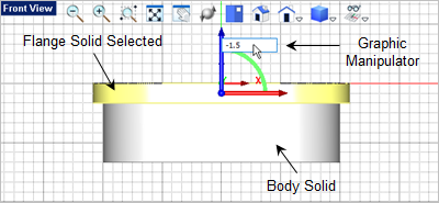
10.Pick on the blue Z Axis arrow to display the input window. 11.Enter -1.5
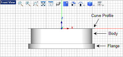
12.Now lets unite the flange with the body. From the Mesh Modeling tab, 13.For the first mesh solid select the body.
14.For the second mesh solid select the flange. The two will be joined into one mesh solid. |