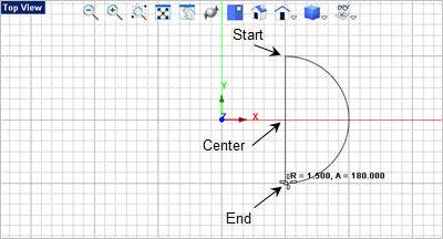
In this step we will model the body by creating an extrusion. 1.Activate the Top View 2.Select the Curve Modeling tab 3.Now select the Arc Center, Start, Angle command. 4.In the Status Bar make sure the Grid Snap is On 5.For the center point select the grid point shown below. The status bar will track where your cursor is located in World Coordinates. Move the cursor until the grid point at 1.5,0,0 is located and pick it. 6.Following the command prompts
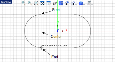
7.For the arc end point move the cursor clockwise and pick the end point shown. You will see that the arc is previewed as you move the cursor. 8.Now we want to draw another arc, press <Enter> to repeat the command and select the center, start and end points shown below.
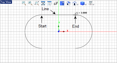
9.Now we want to draw a line to connect the two arcs across the top. From the Curve Modeling tab 10.For the start point for the line select the grid point located at the top end of the arc of the left and then for the end point of the line select the top end of the arc on the right. Optionally, you can set the Object Snap to End Point
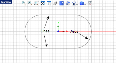
11.Press <Enter> to repeat the Line command
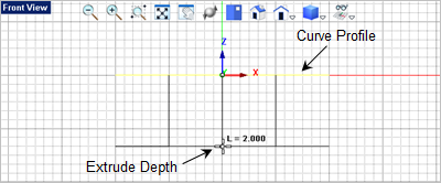
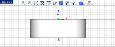
12.For modeling its best that you merge your profile geometry into a single curve entity. 13.Window select the geometry (both arcs and both lines) and from the Curve Modeling tab 14.Now lets create the body by extruding our profile curve. With the curve selected, change to the Mesh Modeling tab 15.For the extrusion distance, drag the cursor down to the Front View
|