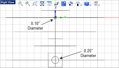
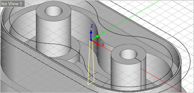
In this step we will create the wall that pass between the two center bosses. 1.Again, activate the Right View 2.From the Curve Modeling tab, 3.For the center point select the grid point shown below. 4.Enter 0.25 5.Press <Enter> again to repeat the command. For the second circle select the grid point shown below and then enter 0.10
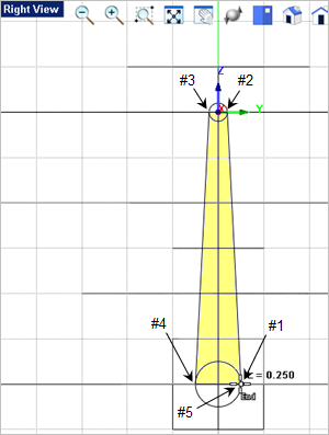
6.Now from the Curve Modeling tab, 7.From the Status Bar toggle on the Quad Point Snap 8.We will be drawing a 4-sided closed polyline that encompasses the yellow area shown in the image below. For the start point of the polyline select the quad point on the right side of the lower 0.25" diameter circle at the #1 location shown. 9.Then continue, by selecting the Quad point located at the right side of the upper 0.10" diameter circle. 10.For the next point in the polyline select the Quad point on the left side of the upper 0.10" diameter circle at the #3 location. 11.Then continue by selecting the Quad point at the #4 location. 12.To complete the polyline select the Quad point at the #1 location where the polyline started. The Polyline
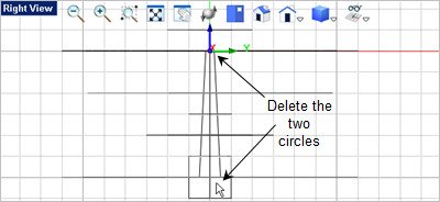
13.Now you can delete the two circles. Just select them and press the <Del> key.
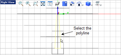
14.Now we will extrude the 4-sided polyline to create the Connecting Wall. First select the polyline we just created.
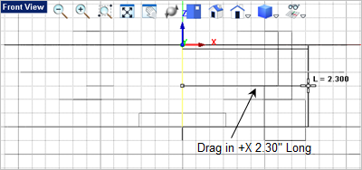
15.Now go to the Mesh Modeling tab 16.Drag the cursor to the Front View 17.The point we want is not on a grid point, so with the extrusion previewed (do not select a point), go to the command prompt
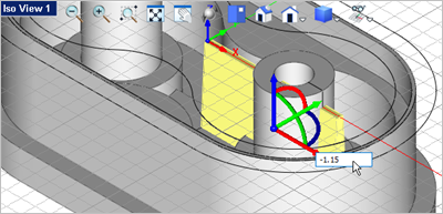
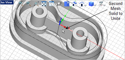
18.Now from Iso View 1
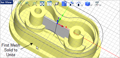
19.Pick the red X Axis arrow and type in -1.15 20.Now lets unite the Connection Wall with the body. Go to the Mesh Modeling tab 21.For the first mesh solid, select the body.
|