 Arc motions (G03/G04) can be posted to your g-code files using the Arc Fitting functionality included in MecSoft’s CAM plugins. Arc Fitting is an option that can be enabled so that arcs can be fitted to otherwise linear motions. This blog post will show you how to enable Arc Fitting and also how to make adjustments that will ensure the arcs you are fitting and posting are within your required machining tolerances.
Contents
Arc Fitting Sequence of Actions
If Fitting Tolerance (t) is too tight (small)
If Fitting Tolerance (t) is too slack (high)
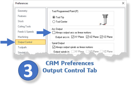
Step 3: The CAM Preferences Dialog
Step 4: How Arc Toolpath Motions are Displayed
Step 5: Post / Test / Adjust as Needed
Step 6: Testing and Adjustments
The CAD/CAM Part
Arc Fitting Overview
Let’s start by providing an overview of how arcs are fitting in MecSoft CAM. You can refer to the following information graphic. It illustrates the basic progression of the steps required for arc fitting and posting those arcs out as G02 (Clockwise Arcs) and G03 (Counterclockwise Arcs). Note that it is important to understand the sequence of events that occur by you as the MecSoft CAM user and by the CAM plugin. The brief sequence is listed below and a more in-depth discussion will follow.
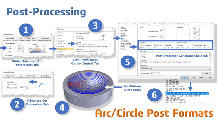
Arc Fitting Sequence of Actions
Step 1: Review the Global Tolerance that you have set for the toolpath operation that you want arcs to be fitted to.
Step 2: From the Advanced Cut Parameters tab of the machining operation dialog, check the box to enable arc fitting and enter the arc Fitting Tolerance.
Step 3: From the Output Control tab of the CAM Preferences dialog, make sure the checkbox “Always output arcs as linear motions” is NOT checked. If this box is checked, no arcs will be posted regardless of any other steps that you take. It is essential not to forget this step.
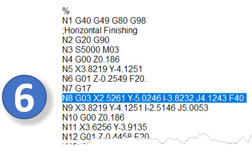
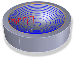
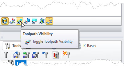
Step 4: When satisfied with your toolpath operation parameters, pick Generate to calculate the toolpath and display it on the graphics screen. Arc motions are in blue by default. If you do not see your toolpath displayed graphically, make sure you have the toolpath operation selected in the Machining Job tree. Also, make certain the Toggle Toolpath Visibility icon is toggled on.
Step 5: Post your toolpath operation, load the resulting g-code file onto your CNC machine, and check for any messages or alarms. You can control the output format of arc motions from the Circles tab of the Post-Processor Generator dialog.
Step 6: If you made any adjustments in Step 5, repost the toolpath operation and perform Step 5 again. Repeat until Step 5 is performed and the g-code file runs on your CNC machine without issues.
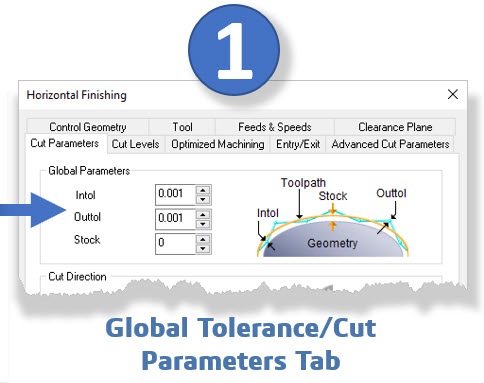
Step 1 Global Tolerance
The Global Tolerance displayed in the Cut Parameters tab of the toolpath operation directly affects the resulting posted g-code file. Look at the dialog icon displayed to the right of the Global Tolerance in the toolpath operation dialog shown below. Global Tolerance determines how close linear motions are to following the actual part surface. A lower (tighter) Global Tolerance produces shorter linear motions and more of them. These are the linear motions that arcs are fitted to.
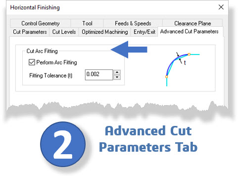
Step 2: Arc fitting Tolerance
Go to the Advanced Cut Parameters tab of the toolpath operation dialog and check the box to Perform Arc Fitting. This box must be checked to output arc motions for this operation. Then enter the Fitting Tolerance (t) value. Just as Global Tolerance determines how close linear motions are to following the actual part surface, Fitting Tolerance (t) determines how close the arc motions follow the linear motions.
How Arcs are Calculated
With Arc Fitting enabled, you see that one arc passes through three linear cut endpoints. These are the toolpath points calculated based on the Global Tolerance value. Then, the chord height between two linear motions and the arc is calculated. If this chord height distance is less than Fitting Tolerance (t) the arc is kept. If it is larger, the arc is ignored.

If Fitting Tolerance (t) is too tight (small)
If the tolerance is too tight, all fitted arcs will be discarded resulting in all linear motions being output. This is calculated when you pick Generate from the toolpath operation dialog.
If Fitting Tolerance (t) is too slack (high)
If the tolerance is too slack, then you may get arcs in places where sharp corners are required by design.
What’s Recommended
We recommend that you set Fitting Tolerance (t) to twice that of your Global Tolerance. If you set your Global Tolerance to 0.001” inches, then set Arc Fitting (t) to 0.002” inches. If the project requires a resulting machining tolerance of 0.001”, then set Fitting Tolerance (t) to 0.001” and then set your Global Tolerance to 0.0005”.
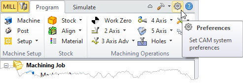
Step 3: The CAM Preferences Dialog
Go to the Output Control tab of the CAM Preferences dialog and UNCHECK the box that says “Always output arcs as linear motions”. If this box is checked, no arcs will be posted regardless of any other steps that you take. It is essential not to forget this step.
Step 4: How Arc Toolpath Motions are Displayed
After you pick Generate from the toolpath operation dialog, you can see which motions are arcs by looking at the colors of the toolpaths. Each motion type is a different color. The default colors are specified in the CAM Preferences dialog and are listed below.
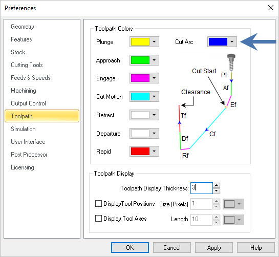
The Toolpath Tab of the CAM Preferences Dialog
Default Colors in 2½ Axis Toolpaths (Arc Motions are in Blue)
Default Colors in 3-Axis Toolpaths (Arc Motions are in Blue)
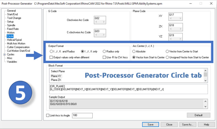
Step 5: Post / Test / Adjust as Needed
Post your toolpath operation and load the resulting g-code file onto your CNC machine. Check for any messages or alarms. If you have messages or alarms on lines in the gcode file that define arc motions, you can control the output format of arc motions from the Circles tab of the Post-Processor Generator dialog as shown below.
Step 6: Testing and Adjustments
If you make any adjustments in Step 5, repost the toolpath operation and perform Step 5 again. Repeat until Step 5 is performed and the g-code file runs on your CNC machine without any alarms or erroneous messages.