 In CNC machining, maintaining consistent tool pressure and motion is the key to surface quality and tool longevity. While many CAM systems allow you to control feedrates on straight lines, the transition into and out of corners—specifically circular arcs—presents a unique challenge. Too much speed in a tight arc can lead to tool deflection, vibration, or "overshooting" the intended path.
Contents
The Physics of the Curve: Why Arcs Need Optimization
The Problem with Constant Feedrates
How Arc Feedrate Optimization Works
1. Programmable Deceleration and Acceleration Buffers
2. Intelligent "Smart Triggering" Logic
3. Limiting Arc Length and Radius
Watch the Webinar Segment: Arc Feedrate Optimization
Introduction
In our latest webinar, MecSoft Corporation introduced a critical enhancement in the 2026 release of VisualCAD/CAM: Arc Feedrate Optimization. This feature is designed to give you more granular control over how your machine behaves in high-stakes areas of the toolpath.
Watch the Webinar Segment: Arc Feedrate Optimization in VisualCAD/CAM
The Physics of the Curve: Why Arcs Need Optimization
To understand the value of this new feature, we must first look at the physics of the cutting tool. When a machine moves in a straight line, the tool engagement (the amount of material the tool is "biting" into) remains relatively constant. However, as soon as that tool enters an arc, the geometry of the cut changes.
The Problem with Constant Feedrates
In traditional CAM programming, a single "Cut Feedrate" is often applied to an entire operation. While this is efficient for straightaways, it creates significant issues during circular interpolation (G02/G03 motions):
•Increased Tool Pressure: As a tool rounds a tight corner, the "wrap-around" effect increases the contact area between the tool and the workpiece. This spikes the cutting forces.
•Inertial Challenges: CNC machines are heavy. Forcing a multi-ton machine tool to maintain 100 IPM (inches per minute) through a 0.1" radius arc is a recipe for mechanical "jerk," which leads to vibration and chatter.
•Heat Accumulation: Higher pressure and friction in the arc generates localized heat. Without a reduction in feed, this heat can lead to work hardening or premature tool dulling.
Historically, VisualCAD/CAM offered toolpath optimization for sharp corners. But the 2026 release brings this same level of intelligence to arcs, allowing the machine to "breathe" as it navigates complex, curved geometry.
How Arc Feedrate Optimization Works
During the webinar, we demonstrated how this new functionality is integrated into the Toolpath Optimization tab. This isn't just a simple "slow down" button; it is a programmable logic suite that gives you complete control over the machine’s behavior.

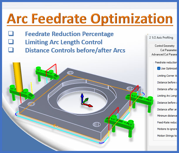
Toolpath Feedrate Optimization tab of the 2-½ Axis Profiling Operation Dialog
1. Programmable Deceleration and Acceleration Buffers
The 2026 update allows users to define specific "buffer zones" around an arc. You can now specify exactly how far before an arc the machine should start slowing down, and how far after the arc it should wait before speeding back up.
•Distance Prior: You can set the tool to decelerate a specific distance (e.g., 0.375") before it even touches the arc.
•Reduced Feedrate: You can define a percentage of the cut feedrate to apply during this zone. In the webinar example, the feed was reduced to 25% of the programmed speed.
•Distance After: Once the arc is completed, the tool maintains that lower, stable speed for a set distance before ramping back up to 100%.

Illustration of how Toolpath Feedrate Optimization works at Arc Motions

Output G-Code Showing Feedrate Reduction and Resumption before and after G02 Arc Motions
2. Intelligent "Smart Triggering" Logic
One of the most critical aspects of this feature is that if every single arc in a toolpath triggered a slowdown, cycle times would skyrocket—especially in High-Speed Machining (HSM) where tangent arcs are used to keep motion fluid.
MecSoft’s logic uses Corner Angle Limits. The optimization only kicks in when the arc represents a change in direction that exceeds your defined limiting angle. If the arcs are tangent and designed for smooth flow, the software recognizes this and maintains the programmed speed, ensuring you don't lose the benefits of HSM.
3. Limiting Arc Length and Radius
Not all curves are created equal. A large radius on a decorative panel doesn't require the same caution as a tight internal corner on a stainless steel mold. The 2026 release includes a Limiting Arc Length option. Users can set a threshold—for instance, 1.0 inch—so that only arcs with a radius smaller than that value will be optimized. This allows you to "set and forget" your optimization parameters, knowing the software will only intervene when the geometry truly demands it.
