
Above we see the speaker cabinet assembly.
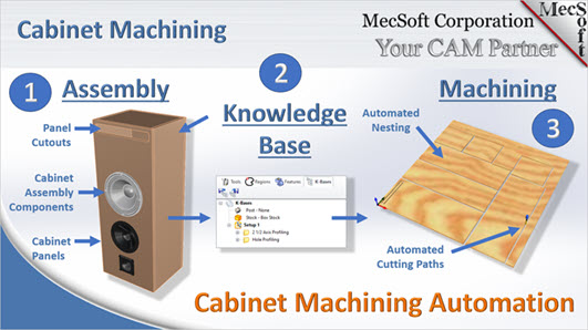
Here we will review the 3-step process of automating the toolpath generation of a nested sheet of flat panel components. For this discussion will use the Speaker Cabinet assembly shown in the infographics below. We have created some videos of this process using the same speaker cabinet assembly. The videos are noted in each section below.
Contents
Watch the Cabinet Machining Automation
Phase 1: Automated Cabinet Layout and Nesting
Watch the Nesting of Components
Phase 2: Automated Knowledge Base of Machining Operations
Create the Toolpath Operations for the Knowledge Base
Watch the Creation of the Knowledge Base
Set the Selection Rules for the Knowledge Base
Phase 3: Automated Sheet Machining
Watch the Cabinet Machining Automation
Watch the Cabinet Machining Automation
Phase 1: Automated Cabinet Layout and Nesting
Cabinet Flat Panel Layout
In this phase the Flat Panel Layout utility included in RhinoCAM MILL Module (or VisualCADCAM) is used to decompose the speaker cabinet assembly and lay each panel out flat in preparation for nesting the components onto a sheet of stock material. In the illustrations below, the panels are laid out along the X axis. Notice that there are interior cutouts on some of the panels.
Above we see the speaker cabinet assembly.

The RhinoCAM Flat Panel Layout utility decomposes the speaker cabinet assembly and lays each panel flat onto the XY plane.
Watch the Flat panel Layout Utility
Cabinet Nesting onto a Sheet
Now that the cabinet panels are laid out flat on the XY plane we can load the RhinoCAM NEST Module. From here we can define the stock sheet as 60” x 60” x 0.75” and then add the component parts and quantities that we want included in the nest. There are many other parameters you can adjust if needed, such as the distance between component parts on the nested sheet. We can then Execute the Nest to see a preview of the nested sheet (bottom left image). Once we are satisfied we can Commit the Nest to generate the nested components (bottom right image)
 A preview of the nested sheet |
 The nested sheet completed |
Watch the Nesting of Components
Phase 2: Automated Knowledge Base of Machining Operations
Create the Toolpath Operations for the Knowledge Base
Now that we have a sheet containing all of the panels in our speaker cabinet, we can move on and create a knowledge base of the machining operations that we wish to use to machine the sheet. A review of the panels shows us that they contain both square and round interior cutouts. To cut these panels we will use one 2 axis Profiling operation for the square cutouts and one 2 axis Hole Profiling operation for the round cutouts.
These toolpath operations are used when cutting our sheet of nested components so we need to make sure they represent the exact way that we wish to machine, including cutting parameters, cut level parameters, entry/exit, etc. It’s a good idea for us to simulate and review each toolpath operation before continuing further. While you can edit these toolpaths once they are added to the knowledge base, it is good to get it right the first time.
Watch the Creation of the Knowledge Base
Set the Selection Rules for the Knowledge Base
Once we’re confident that each operation is correct to our liking, we can save the operations to a Knowledge Base KB file using the Save to KB command on the Program tab.
Now it is time to add the selection rules to each of our two operations in the Knowledge Base. This step will allow the operations to generate successfully once the knowledge base is loaded into the RhinoCAM Machining Job of our nested sheet file.
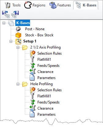
First we will load the Knowledge Base file into the K-Bases tab of the RhinoCAM Machining Objects Browser. This is shown here on the right. Notice that there is a flag next to the Selection Rules icon under each operation.
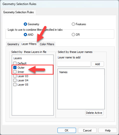
Each operation in the Knowledge Base can be set to automatically retrieve control geometry. This automated selection can be made by Geometry type, Layer name, Color or Feature type. In this case we will be selecting control geometry from two specific layers named “Inner” and “Outer”. First we create the two named layers in our Rhino file. Then we click on the flagged Selection Rules icon under each operation. This will display the Geometry Selection Rules dialog shown below. In the dialog, select the Layer Filters tab and you the two named layers that we created. For the 2 axis Profiling operation we will select the layer named Outer. Then for the 2 axis Hole profiling operation we will select the layer named Inner.
It is important to take a moment here and check to make sure your layer names are correct and that each layer is assigned to a specific operation in the Knowledge Base. Pick OK when you are done to close the dialog.
Phase 3: Automated Sheet Machining
If you have stayed with us this far, congratulations! We’re now ready to automatically generate the toolpaths needed to machine our sheet of nested speaker component panels.
What We have Done So Far
Let’s take a moment to review what we have done so far:
1.We used the Flat Panel Layout utility in RhinoCAM MILL (or VisualCADCAM) to decompose our speaker cabinet assembly onto the XY plane.
2.We used the RhinoCAM NEST module to nest the speaker panels onto a 60” x 60” x 0.75” sheet.
3.We created a Knowledge Base of the toolpath operations we wish to apply to our sheet of nested components.
4.We assigned selection rules to each operation in the Knowledge Base to automatically select from two existing layers
What Happens Automatically
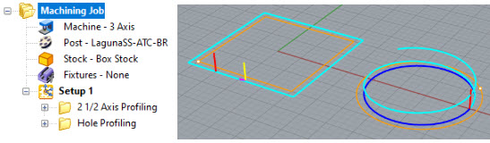
When loaded, the Knowledge Base file automatically populates the Machining Job with two operations. These are: 2 Axis Profiling and 2 Axis Hole Profiling.
When Setup 1 in the Machining Job is generated, the knowledge contained within our two operations automatically grabs the geometry from the correct layers and successfully regenerates the operations and displays the resulting toolpaths on the graphics screen.
!")
Now consider this process being applied to a larger project with hundreds of nested components and you begin to see the benefits of Knowledge Base machining with RhinoCAM (or VisualCADCAM)!