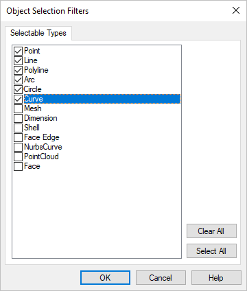
Your almost done!! In this step we want to create some section curves in the Top and Right side views. The section will appear on the XY Plane (for the Top view) and on the ZY Plane for the 1.First lets move all of our curves onto a separate layer and hide them. From the 2.From the Object selection filters dialog, check the boxes next to Point, Line, Polyline, Arc, Circle and Curve and then pick OK. All of the curve related entities will now be selected.
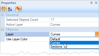
3.From the Status Bar select the Properties icon
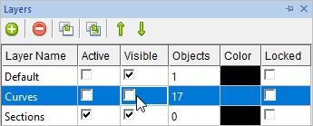
4.This dialogs reports that a total of 17 entitles are selected. In the Objects section drop down the menu for Layer and select Curves from the list of layers. 5.Now from the Status Bar select the Layer Manager icon
6.From the Layer Manager, under the Active column, check the box to make the layer named Sections the active layer. 7.You can close the Properties and Layer managers by allowing them to auto-hide or pick the "X" icon to close them. 8.Now we're ready to create the section curves. First activate the 9.Go to the
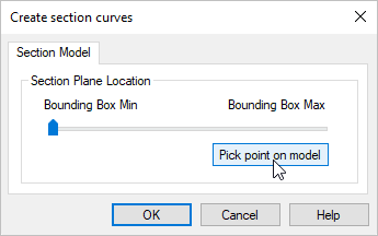
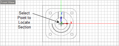
10.If you move the slider you will see a highlight of the section display in all views. 11.Now from the dialog select the Pick point on model button. The dialog minimizes allowing you to select a point. From the Front View, select the XY origin grid point to locate the section.
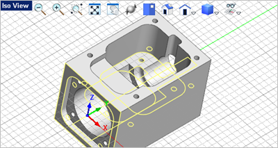
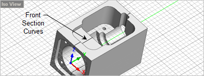
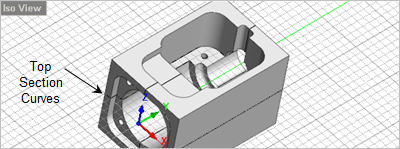
12.The dialog reappears and you can pick OK to close it. 13.Now activate the 14.Go to the 15.From the Create section curves dialog, select the Pick button and then select the same grid point, 0,0,0 origin in the 16.You will now notice that section curves were created in both the XY Plane and the YZ Plane.
17.Save the file as Connector_Block_Completed.vcp. |