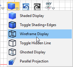
In this step we will draw two concentric circles and then extrude them to model the circular tube that sits at the base plate. 1.Select the Top View 2.From the View Toolbar drop down the Display menu
3.Now from the Curve Modeling 4.For the center point select the grid point at 0,0 center of the drawing. 5.Now for the circle diameter you can select the grid point shown below or type in 3 and press <Enter>. A circle 3" in diameter is drawn.
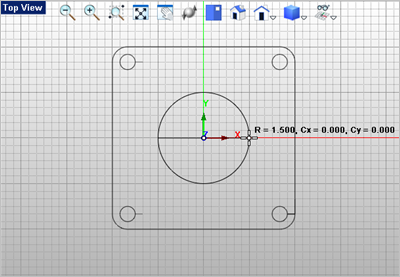
6.Now repeat the command, this time drawing a circle with a diameter of 2.5" in diameter.
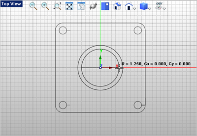
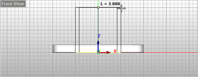
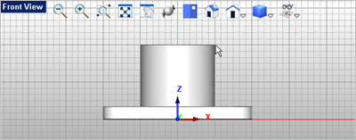
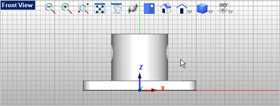
7.Once the two concentric circles are drawn, select them both. You can window select them or while holding down the <Ctrl> key, just pick both of them. 8.With the two circles selected, go to the Mesh Modeling 9.Now move the cursor to the Front View
10.The center tube is now created and shown in each window.
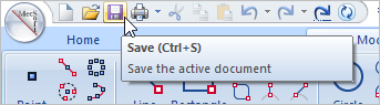
11.Save your work by selecting the Save icon from the Quick Access Toolbar.
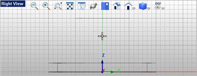
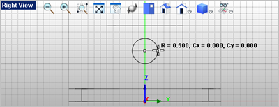
12.Activate the Right View 13.From the View Toolbar, drop down the Display
14.From the Curve Modeling 15.For the center point of the circle, select the grid point shown below.
16.Now for the circle diameter you can select the grid point shown below or enter 1.0 for the diameter.
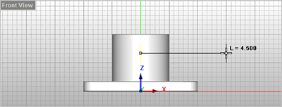
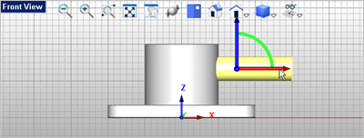
17.Now select the circle you just created, then go to the Mesh Modeling 18.For the length of the cylinder move the cursor over to the Front View
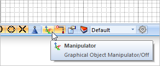
19.Now select the cylinder and toggle the display of the Graphic Manipulator
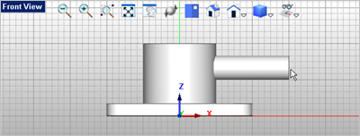
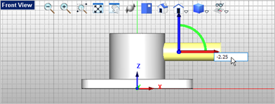
20.With the cylinder selected pick on the red X axis of the Graphic Manipulator to display the input box and enter -2.25
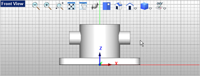
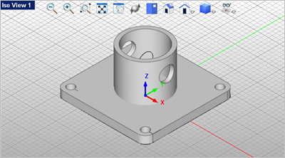
21.You can toggle the Graphic Manipulator 22.From the Mesh Modeling 23.For the first mesh select the tube.
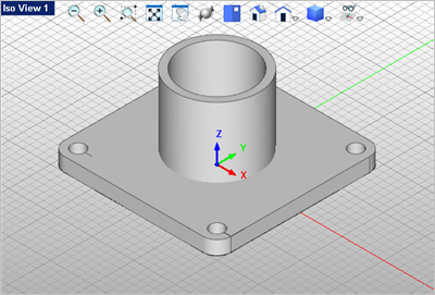
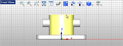
24.For the second mesh select the cylinder. The hole is created in both sides of the tube.
|