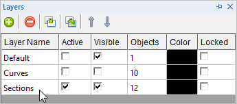
Congratulations, our part is now nearly complete! However, we do want to create cross-section curves that will aid you when it comes time to create a detail drawing of the part. Section curves are drawn parallel to the active Viewport. So the first step is to select the view that you want the section to be parallel to. We want to create three sections, one through the center parallel to the Front View and another two through each boss parallel to the Right View. 1.First lets again create a new layer and make it the active layer so that the section curves will be assigned to that layer automatically when they are created. 2.Display the Layer Manager 3.Create a new layer and name it Sections and also make it the active layer. The Layer Manager should look like this:
4.Now go to the Curve Modeling tab
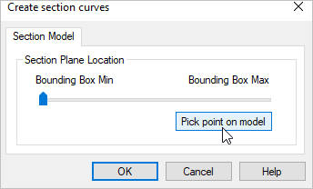
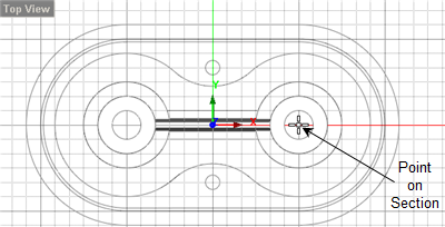
5.First select anywhere in the Front View 6.Now if you move the slider in the dialog you will see the section curves move along the part. 7.We want the location of the section to be precise so lets pick the Button that says "Pick point on model". 8.Now from the Top View
9.When you pick the point at the center of the boss, you will see the section curves display on the part. They pass through the center parallel to the Front View just like we want. 10.Now press the <Enter> key to repeat the section command and then activate the Right View 11.From the Create section curves dialog select the button again that says "Pick point on model". 12.Now from the Top View
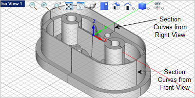
13.When you pick the point at the center of the boss, you will see the section curves display on the part. They pass through the center of the boss parallel to the Right View just like we want.
14.Save the file as Insert_Completed.vcp. |