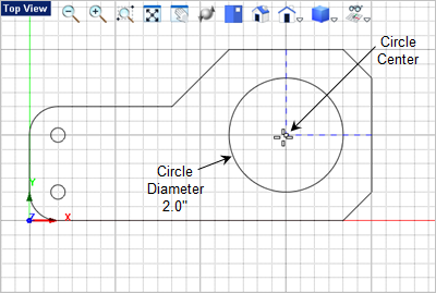
In this step you will learn a few additional curve creation and curve editing commands. 1.Lets draw another circle. From the Curve Modeling 2.For the center point of the circle use the Visual Aids 3.For the circle diameter enter 2.0 in the command window
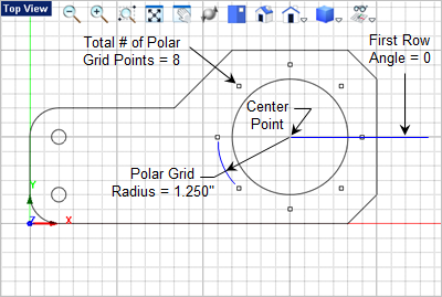
4.Next we will draw a polar array of points around the circle we just drew.
5.From the Curve Modeling 6.For the total number of points on the circumference, enter 8. 7.For the angle of the first row about the X Axis enter 0. 8.Pick the center point for the polar grid or enter the coordinate values. We want the points centered around the 2" circle we just drew, so set you Object Snap to Center Point 9.For the polar grid radius, enter 1.250 and then press <Enter>. The polar grid of points will be created around the circle as shown below.
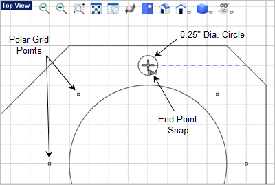
10.For this exercise we will also add the polar array of circles. From the Curve Modeling 11.For the center point, make sure the End Point Snap 12.For the circle radius enter 0.25 and then press <Enter>.
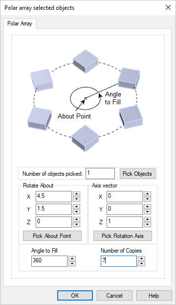
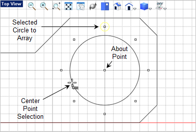
13.Now we will duplicate the circle by creating a polar array. First select the circle you just created. 14.Then from the Modify / Transform 15.Select the Polar Array
16.The Number of Objects field should be 1. This represents the circle that you have selected. 17.Under the Axis Vector, the values should be X0, Y0, Z1. 18.Under the Rotate About section, select the Pick About Point button. The dialog will minimize and wait for you to select a point. 19.From the Status Bar activate the Center Point Object Snap 20.Now move the cursor over the 2" diameter circle until the center point is displayed and then selected it.
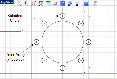
21.The dialog will re-appear with the XYZ coordinated entered for the Rotate About section. The value should be X4.5, Y1.5 and Z0. 22.For the Number of Copies field enter 7. 23.The Angle to Fill field should be 360. 24.Now pick OK to close the dialog and the array should be drawn and selected. 25.Press <Enter> to accept the array and your drawing should look like the illustration below. If not, select the Undo
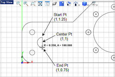
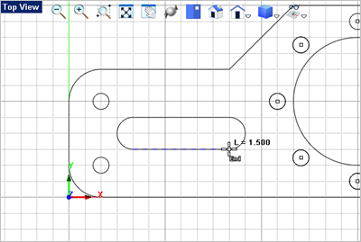
26.Now we will drawing a slot. From the Curve Curve Modeling tab 27.In the Status Bar make sure the Grid Snap is On 28.For the center point select the grid point shown below or enter 1,1 in the command window and press <Enter>. 29.Following the command prompts. It says to select the start point of the arc. Locate and select the start point shown below or enter 1,0.75 in the command window and press <Enter>.
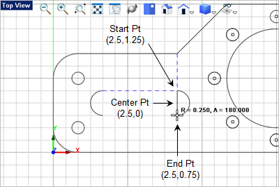
30.For the arc end point move the cursor counter-clockwise and pick the end point shown or enter 1,0.75 in the command window 31.Now we want to draw another arc, press <Enter> to repeat the command and select or enter the center, start and end points shown below.
32.Now we want to draw a line to connect the two arcs across the top. From the Curve Modeling tab 33.For the start point for the line, set the Object Snap to End Point 34.Press <Enter> to repeat the Line command and select the start and end of the bottom line of the slot. Your drawing should look like this:
|