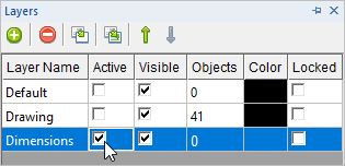
In this step you will learn how to place dimensions on the drawing. 1.Start by using the middle mouse wheel to zoom out to leave yourself plenty of room to place your dimensions. If your mouse does not have a middle wheel, select the Zoom Out 2.Now change the active layer. From the Status Toolbar select the Layer Manager 3.From the Layer Manager go to the Active column and check the box next to Dimensions to make it the Active Layer.
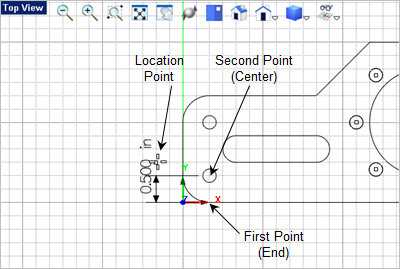
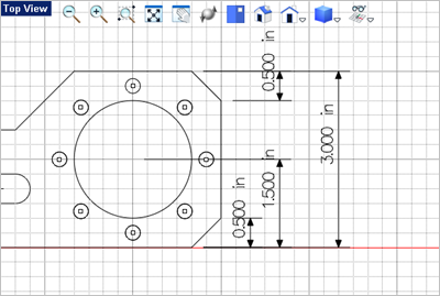
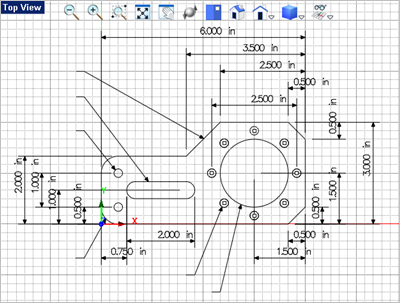
4.From the Dimension 5.Activate the Object Snaps required (End 6.Select the first and second points that you wish to dimension. 7.Then select a point to locate the dimension. refer to the illustration below:
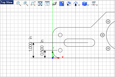
8.Press <Enter> to repeat the command. 9.Select the first, second and location point for the dimension as shown below:
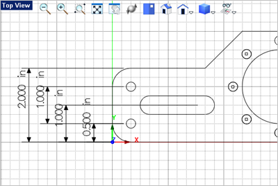
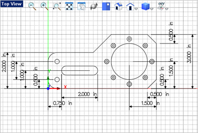
10.Repeat the command to create three additional vertical dimensions on the left as illustrated below:
11.Repeat the command to create three additional vertical dimensions on the right as illustrated below:
12.Now we will create the horizontal dimensions. From the Dimension 13.Select the first second and location points to create the lower horizontal dimensions shown below:
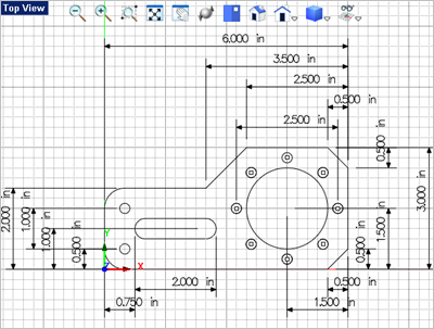
14.Repeat the command to create the upper horizontal dimensions shown below:
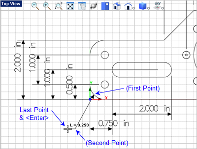
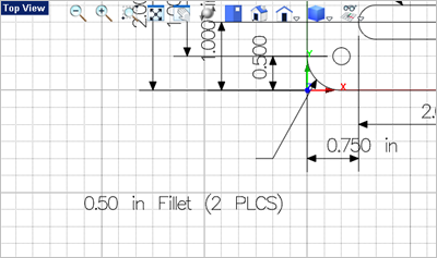
15.Now we will create some leader lines. From the Dimension 16.The first command prompts says: "Enter the text string." We will add the annotation separately so you can press <Enter> to continue. 17.The next prompt says: " Pick point or enter coordinates x,y, and z" Change the Object Snap to Near 18.Then pick additional points to define the leader line and the press <Enter> or right-click to end the command. The points to pick are shown in the illustration below:
19.Now repeat the Leader Line command and add the leader lines shown below:
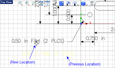
20.Now we will add the annotation text. From the Dimension 21.For the text string, at the command prompt
22.Now select the text you just created and left-click-hold to drag it into position to the left of the leader line as shown below. If you toggle the Grid Snap
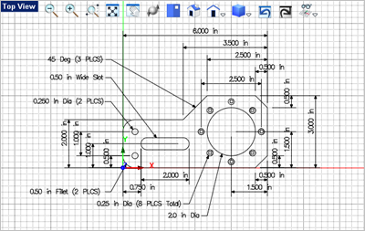
23.Repeat the Annotation command to create the additional leader text shown below: 24.Save the file as Drawing_and_Dimensioning_Completed.vcp.
Congratulations you have completed this exercise! |