The following Cut Parameters tab allows you to define the roughing parameters for the current 2½ Axis Deburr operation. You can set Global Parameters, Edge Limits, Cut Direction, Cut Side, and Corner Handling via this tab of the operation dialog. The Global Parameters section allows you to set the Tolerance value to be used in machining. Refer to each option below.
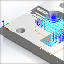
| 2½ Axis Deburring Example Using a Ball Mill |
 2½ Axis Deburring using a Ball Mill |
 Dialog Box: 2½ Axis Deburring |
The Global Parameters section allows you to set the tolerance value to be used in machining. A uniform thickness or stock that needs to be left around the part can be specified here. Tolerance This is the allowable deviation from the actual part geometry plus the Stock allowance (if any). In 2 Axis methods, this Tolerance is applied to XY motions only.  Tolerance
Stock In 2 Axis, Stock is measured in the X and Y directions but not in the Z direction. This is reflected in the illustration below. For roughing operations, set Stock to the amount you want to leave on the part. For finishing operations set this value is zero.  Stock Compensation Compensation can be used to compensate for tool wear. Select AUTO/ON to tell the controller to enable Compensation for this tool. The compensation direction, left or right, is determined by the Cut Direction selected (Climb or Conventional). The actual Compensation offset value is defined on the CNC controller. Cutter Compensation also needs to be enabled in your selected Post Processor. |
Sharpness Angle Threshold This is the minimum face-to-face angle considered a "sharp edge" to be automatically detected for processing. In the example below, the Sharpness Angle is considered to be 90 degrees because the walls are vertical. A Sharpness Angle larger than 90 degrees would be a drafted or tapered wall. 2½ Axis Deburring using a Ball Mill Min Edge Length Use this parameter to limit the edge lengths considered for deburr. Edges shorter than this length will be ignored during processing. Max Edge Length Use this parameter to limit the edge lengths considered for deburr. Edges longer than this length will be ignored during processing. |
The following Deburring Parameters are available: Width For a deburr width, select Width and then enter a distance. Width will offset the toolpath to the Right or Left depending on the Cut Direction specified in this dialog. You can only specify either a Width or a Height, not both. Height For a deburr height, select Height and then enter a distance. Height will offset the toolpath downward in Z. You can only specify either a Width or a Height, not both. Tooltip Clearance This is a vertical depth value that you can add to make sure the tip of the tool clears the bottom edge of the deburr. This will remove any possible material and/or witness lines. Note that the image below shows a Vee Mill but you can also use a Ball Mill, Chamfer Mill or Taper Mill. Note: This option is not enabled for "Flat End" tools such as flat mills or chamfer/taper tools with a flat bottom.  Tool Tip Clearance |
Climb (Down Cut) Select Climb (Down Cut) and the tool will be maintained in a downward motion into the stock. ") Climb (Down Cut) Conventional (Up Cut) Select Conventional (Up Cut) and the direction of the tool will be maintained in an upward motion out of the stock. ") Conventional (Up Cut)
|
 One of the basic concepts to understand in any milling operation is
 This determines the side of the curve to be cut. Right / Left Right or Left determines the side of the curve to cut. This can be set for both open and closed curves. Right or Left is determined by the start point and direction.  Cut Start Side Note that these Right/Left parameters only applies when Machining Regions (i.e., curves and/or surface edges) are added to the Control Geometry tab for this operation. |
Use these options to determine how the Deburr toolpath is defined at sharp corners. Select from the following options: Roll Around Corners This is the default Corner Handling. The deburr tool rolls around a sharp corner. Depending on the toolpath Tolerance, this method can cause rounding of the sharp corner. NOTE: This option must be used if your Control Geometry is not closed or is not a ploy-line!  Round Break Into Segments This Corner Handling Type will force the tool to stop when the tool center aligns with a corner, retract and begin again when the tool center aligns with an adjacent corner. Refer to the illustration below.  Deburr Break |