 If you’ve ever tried to machine a complex curved surface that wraps around a rotary axis, you know the struggle. Traditional 3D toolpaths often require a high-quality 3D model, complex containment boundaries, and endless "trial and error" to get a clean finish.
Contents
What is 4-Axis Extrusion Machining?
Why is 4-Axis Extrusion Projection Machining Better?
Tips for 4-Axis Extrusion Machining Success
What is 4-Axis Extrusion Machining?
What makes these methods different from traditional 4-axis?
What types of parts are best suited for these methods?
Do I need a 3D part model to use Extrusion Machining?
How does 4 Axis Extrusion machining work?
How does this compare to Drive Surface Machining?
What is the difference between Extrusion and Projection methods
Are there any risks with 4 Axis Projection Machining?
How does the simulation speed compare to older methods?
Can I limit the toolpath to specific areas of the part?
Introduction
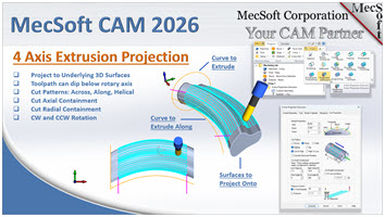
With the release of RhinoCAM 2026, MecSoft has introduced a paradigm shift: 4-Axis Extrusion Machining. This strategy allows you to create high-efficiency continuous motions without even needing a 3D part.
In this deep dive, we’ll break down the two main workflows —Extrusion and Projection— to show you how to cut programming time in half while improving surface quality.
Watch the Demonstration Here
This guide is based on the technical demonstrations provided in our recent webinar segment.
What is 4-Axis Extrusion Machining?
As demonstrated in the webinar, 4-axis extrusion is a "geometry-driven" strategy. Instead of calculating toolpaths based on a mesh or a surface model, it uses two 2D or 3D curves to define the motion.
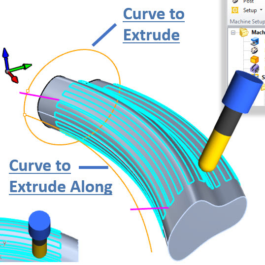
The Two-Curve Workflow
•Curve to Extrude: This is the cross-section of your cut. It defines the profile of the tool's movement.
•Curve to Extrude Along: This is the path the cross-section follows. In a 4-axis setup, this path can be on or off the rotary axis or both.
Why It’s a Game Changer
The primary advantage of the Extrusion-only method is that no 3D part is required. If your desired part is an extrusion, there is no need to model the actual part, saving you precious design time.
Why is 4-Axis Extrusion Projection Machining Better?
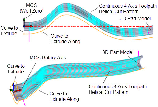
While the Extrusion-only method takes the profile curve and follows a path, Extrusion Projection takes it a step further by projecting the extruded toolpath onto an underlying 3D model. This method is ideal for parts that do not follow exactly the shape of the extrusion. In the illustration below you see that the Curve to Extrude is roughly the shape of the 3D part. Note that the 3D part model does not follow the Rotary Axis. In practice, you can have any 3D model shape and then strategically position the Curve to Extrude and Curve to Extrude Along so as to “Wrap” a toolpath around the part!
How It Works
•The Benefit: The software perfectly handles the complex math of wrapping the toolpath onto the part model.
•The Application: Use the Extrusion Projection method when your part is not a perfect extrusion or if it does not follow or encompass the Rotary Axis.
Tips for 4-Axis Extrusion Machining Success
Here are some tips you can use to save time, ensure accuracy and general success when utilizing the 4 Axis Extrusion Machining methods in RhinoCAM and VisualCADCAM.
1.Ditch the 3D Part for Roughing: You don’t need a solid model to start clearing material. Use 4-Axis Extrusion to create a "roughing wrap" using simple curves to save CPU processing time.
2.Utilize Helical Cut Patterns: To avoid "witness marks" (small lines where the tool starts and stops), select the Helical pattern. This keeps the tool in constant contact with the material in a continuous spiral as shown in the illustrations above.
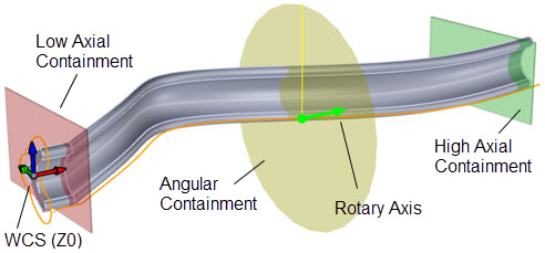
3.Control the Axial Containment: You can use the start and end points of your "Extrude Along" curve to precisely limit where the tool moves. You can also use the Axial Containment controls within the Cut Parameters tab of either extrusion method dialogs.
 Dialog Box: Cut Parameters tab, 4th Axis Extrusion Operations |
4.Set Z-Zero to the Rotary Center: For continuous motion, always set your Z-zero to the center of your 4th axis. This ensures that the "extrusion" math stays perfectly concentric to your stock.
|
5.Leverage Radial Containment: You can specify a “Do not cut below” minimum radius. This is perfect for quick radial roughing ensuring the tool doesn't dive below a containment radius.
6.Optimize Stepover for Finish: Because these toolpaths are so smooth, you can often use a slightly larger stepover than you would in 3-axis, as the rotary motion helps "blur" the scallop lines. The Helical cut pattern also helps in this regard. See the Cut parameters tab shown above.
7.Select the Right Post-Processor: Ensure your post-processor supports G93 (Inverse Time Feedrate). This is critical for 4-axis extrusion because the linear speed of the tool must stay constant even as the rotation speed changes.
Summary of Key Features
•No 3D Part Needed: Saves hours of modeling time.
•The part and Toolpaths can dip below the rotary axis: Essential for specialized offset machining.
•Multiple Cut Patterns: Choose between Across, Along, or Helical.
•CW and CCW Rotation: Total control over the spindle and rotary direction.
By mastering these new 4-axis Extrusion machining strategies in RhinoCAM & VisualCAD/CAM, you aren't just cutting parts—you're optimizing your entire shop's workflow!
Frequently Asked Questions
1.What is 4-Axis Extrusion Machining?
4-Axis Extrusion Machining is a new toolpath method designed for parts with a constant cross-section that follow a sweeping path. Unlike traditional methods, it does not require a 3D part model; it generates a toolpath using only a profile curve (the cross-section) and a rail curve (the path it follows).
2.What makes these methods different from traditional 4-axis?
A key advantage is that the toolpath can dip below the rotary axis, which is a limitation in many other CAM products.
3.What types of parts are best suited for these methods?
The 4 Axis Extrusion methods discussed in this article are ideal for complex geometries that do not follow a straight a center line, such as:
Woodworking: Sculpted chair legs or filigrees
Industrial Design: Deco artwork and complex curved surfaces
Non-centered parts: Parts that are not wholly centered on the rotary axis
4.Do I need a 3D part model to use Extrusion Machining?
No. One of the benefits is that you do not need a 3D model for 4 Axis Extrusion machining. You only need a profile curve and a rail curve to generate the toolpath.
5.How does 4 Axis Extrusion machining work?
The software takes a specific profile (cross-section) and "sweeps" or extrudes it along a rail curve. The rail curve can be any shape, such as an arc or a complex sweeping curve.
6.How does this compare to Drive Surface Machining?
4 Axis Extrusion Machining is significantly faster to calculate because it doesn't need to pull normals from a surface model. It also resolves issues with "stepovers" in vertical areas that occasionally occur in Drive Surface Machining.
7.What is the difference between Extrusion and Projection methods
While the Extrusion method creates a toolpath based purely on curves, the Projection method projects that extruded toolpath down onto an actual 3D part model (mesh or surface) allowing for more varied complexity in the resulting machined part.
8.What should I consider when choosing a profile for Projection Machining?
It is recommended that your profile curve closely approximates the shape of the underlying part. Using an offset of the part’s actual profile helps ensure a more continuous and stable toolpath.
9.Are there any risks with 4 Axis Projection Machining?
Yes. If the profile curve is too different from the underlying part geometry, or if the part is extremely convoluted, it can cause "loops" or weird behavior in the toolpath.
10.How does the simulation speed compare to older methods?
The simulation for these 4 Axis Extrusion methods is very efficient especially when using the Tr–Dexel simulation method in RhinoCAM 2026 (EXPERT and higher configurations). In the webinar demonstration, three complex toolpaths were simulated in about 10 seconds, whereas older polygonal methods might take 2 to 3 minutes.
11.Can I limit the toolpath to specific areas of the part?
Yes. These methods support standard axial containment and cut parameters, similar to 4-axis parallel finishing, allowing you to restrict the machining to specific sections of your part.
Watch the Demonstration Here
This guide is based on the technical demonstrations provided in our recent webinar segment.