Introduction
The TURN Module in MecSoft CAM’s RhinoCAM and VisualCADCAM supports 2½ Axis Turning Centers and supports the most comment Turning toolpath strategies including Roughing Finishing, Grooving, Threading and Parting-Off operations. In this article we will discuss the Turn Threading operation and its support for the most common canned threading cycles on Fanuc controllers. This discussion covers the procedures needed to CAM program threads in the TURN Module, from control geometry to post-processing.

TURN Threading in Practice
The Machine Tool Setup
The Setup procedure begins at the Lathe command located on the Program tab of the TURN Machining Browser as shown below. The Machine Tool Setup dialog provides the basic parameters for the TURN Setup including Maximum RPM, Tool Change Position and Travel Limits. You can see our parameters in the dialog below.

Locating the Machine Tool Setup Command

The Machine Tool Setup dialog
The Post-processor
In this step we select a post-processor to match the 2½ Axis Turning Center’s Controller software. In this case we are selecting a Fanuc post which is one of the most common controller software for Turning centers. We have customized one of our legacy Fanuc posts for this article. It is listed as the Current Post Processor in the dialog below.

Locating the Post command from the Program tab of the TURN Machining browser

The Select Post-Processor dialog
Control Geometry for Turning
In the TURN Module, part geometry can be either a 2D drawing or a 3D surface model. In the case of a 2D drawing, the geometry define the cross-section of the Turned part. For a 3D model, the Turn Part is defined by extracting the 2D cross-section profile. In both methods, the cross-section profile is considered the Control Geometry for all Turning operations in the Setup. In this exercise we are defining the Turn Part from a 2D drawing.
The 2D Dimensioned Drawing
The dimensioned drawing below illustrates a cross-section of the resulting Turned part. When using a 2D drawing for Turning, the geometry representing the part cross-section must be an accurate representation. Prior to drawing or importing the 2D drawing make sure the CAD unit tolerances are set to at least 5 decimal places (0.00001). In RhinoiCAM, the drawing tolerance is set from the Units tab of the Tools > Options dialog. In VisualCADCAM it is set from the Tools & Units tab of the Options dialog. Our 2D drawing is illustrated below.

The 2D cross-section drawing of the Turn Part
The Accurate 2D Cross-section Profile
From our 2D Dimensioned drawing we have removed all CAD entities except for the profile geometry. Because our part has internal cutouts that pass completely through the part, we have moved the profile such that the turn part axis is aligned with the CAD World X Axis (in red). We have also moved the right side of the profile so that it lies on the CAD World Y Axis (green). The profile must also lie on the XY plane. Note that we are referring to the CAD WCS (World Coordinate System). This is not to be confused with the MCS (Machine Coordinate System which we will be defining shortly. The 2D profile is shown below.

The 2D Cross-section profile geometry
Defining the TURN Part
With our accurate 2D cross-section profile positioned we can now define it as our TURN Part. This is done using the Select Turn Part command on the Program tab of the Turn Machining Browser. This will display the Select Part Geometry for Turning Operations dialog shown below. Notice that the dialog is divided into 2 parts, Part Solid/Surface(s) and Part Curve(s). Since we are using a 2D Profile, we pick the Select Curve(s) button under the Part Curve(s) section of the dialog. As prompted, we select our 2D profile and press <Enter>. The profile is then added to the Select Machining Feature(s) list as Region 1. Refer to the dialog below.

The Select Part Geometry for Turning Operations dialog
Now we pick Save from the dialog and see that the Turn Part model is now displayed on the screen. You can also see the 2D cross-section profile highlighted in orange. Refer to the illustrations below.

The Turn Part is defined using the cross-section profile and the Select Part Geometry for Turning Operations dialog.
Defining the TURN Stock
The next step is to define the Turn Stock model. For this we go to the Stock menu located on the program tab and we select Cylinder Stock to display the dialog shown below.

The Stock menu with Cylinder Stock selected

The Create Cylindrical Stock Model dialog
The dialog shows the actual outer radius and length of the part based on the Turn Part that we just defined above. We will add some distance to both of these dimensions. For the Radius (R) we will enter 2.1875 and for Length (L) we will enter 4.500. This will provide some extra material to ensure that the completed part has a good surface finish when completed. Notice the Inner Dimensions are set to zero. This is fine since we machining the Inner Diameter out.
Picking OK from the dialog will create the stock model shown below.

The Turn Stock model is shown here with extra material add to the diameter and the length. Note:The ¾ diameter view of the stock is set from the Simulation tab of the CAM Preferences dialog in the TURN Module.
Aligning the Stock with the Part
In the TURN module, it is recommended that you align the Stock model so that it is flush with the left side of the part as it is shown in the illustration above. This is done from the Align command located on the Program tab as shown below.

The Align command on the Program tab of the Turn Machining Browser
From the Align Part and/or Stock Geometry dialog select Left and then pick OK.

Z Alignment is set to Left in the Align part and/or Stock Geometry dialog
Defining the Work Zero for Turning
The Work Zero in the TURN module is where you plan to zero out the Turning Center. This usually lies on the right-most side of the stock on the rotational axis. Note that the left side of the stock is the spindle chuck.

The Work Zero command on the program tan of the TURN Machining Browser
Selecting Work Zero from the TURN Machining Bowser will display the Work Zero dialog shown below. We select Set to Stock Box and and for Zero Face we select Right Most and then pick Generate.

The Work Zero dialog allows you to define where you plan to set the machine zero on the Turning Center.
The illustration below shows where the Work Zero will be located. It is very important that you understand the difference between the CAD WCS (World Coordinate System) triad and the CAM MCS (Machine Coordinate System) triad. Note that the CAM MCS Z Axis is aligned with the CAD WCS X Axis.

The Work Zero is located on the right side face of the Stock Box
TURN Operations
While this article covers Turn Threading, there are many Turn operations that will precede it in the Machining Job. The reason threading is one of the last operations performed is due to surface finish and quality. The last thing you want is extracted stock material damaging those perfect threads that you just cut. Plus, unlike in Milling, in Turning Centers it is more difficult to channel away the extracted workpiece stock so finishing operations are always performed last.
For this part, the following roughing and finishing TURN operations were performed first:

The TURN Threading operation is next to the last operation performed
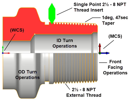
Thread (2½ - 8 NPT External Tapered Thread)
This part requires a 2½“ – 8 NPT tapered external pipe threads. For Turn Threading, the profile geometry must be drawn to the outer diameter of the thread and include the taper. This is critical to get the correct thread after machining. The illustrations below shows where the threads are located on the dimensioned drawing and in the 2D profile used to define the Turn Part.

The location and dimensions for the 2½ – 8 NPT external threads
It is critical that the profile geometry match the major diameter of the 2½” – 8 NPT external thread. In this case it is the 2.884 diameter. It is also critical tha the taper angle of 1 degree, 41 seconds be represented in the profile. If these two dimensions are not accurate, your thread will not be cut correctly. |
Thread Insert Parameters
We will be using a single point thread insert cutting tool for this guide. The Create/Select Tool dialog and and thread parameters are shown in the dialogs below. It is very critical that you know and understand YOUR requirements, including which threading cycles your Turning Center and perform, the thread size dimensions and cutting parameters. You can look this information up using any of the available AI tools such as Grock (X.com), Gemini (Google) or ChatGPT (ChatGPT.com)

The Create/Select Tool dialog showing tool insert dimensions and properties

Composite view of the Create/Select Tool dialog showing insert dimensions, Properties and Feeds & Speeds
Thread Parameters
There are two tabs in the TURN Thread operation dialog that are key to defining our 2½ – 8 NPT external thread. These are the Thread Params tab that controls the definition, size and constraints of the thread and the Thread Cut Params tab that controls the type of Threading cycle that is posted to the G-Code file.
The Thread Type is set to Outer Diameter. The Thread Definition includes the Start and End point of the thread. We used the Pick button to select these two points. The Start Point is located on the profile to the right of the o-ring groove (shown in green) and the End Point is located at the end of the taper. We want the thread to extend out past the chamfer at the tapered end so we have pre-positioned a point at the theoretical end of the taper (shown in red below).

Here we see the Start and the End points of the external thread

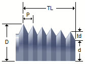
The Thread Params tab of the Turn Thread operation dialog
Two Clearance parameters are provided in the dialog. They allow you to control both the X and Z Clearance. Both are set to 0.5 and 0.05 respectively. Because we are defining a Tapered thread, we make sure the box labeled Always create thread with no taper is not checked. Additionally, the dialog allows us to define the Thread Dept (td) which is 0.1 and the Thread Pitch (P) which is 0.125. These dimensions adhere to the standard 2½ -8 NPT external thread specifications. We are also specifying a Right Hand thread. The dependent parameters Thread length (TL), Major Diameter (D) and Taper Angle are each derived from the Start and End points we picked from the 2D profile.
Thread Cut Parameters
As mentioned previously, the Thread Cut Params tab controls how the G-Code is formatted for threading. The format selected will depend on the capabilities of CNC Turning Center used and operator preferences. The dialog supports multiple canned cycle formats. A Canned Cycle is a piece of G-Code that tells the Turning Center to use one of its predefined cycles for cutting the thread. What follows is a brief description of each of the Thread Cycle types supported by the dialog. What follows is an over-simplified discussion of each of the threading G-Codes supported by the dialog.

The Thread Params tab of the Turn Thread operation dialog
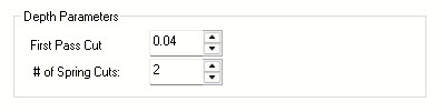
Depth Parameters
This section of the dialog controls the cutting depth of the thread. First Pass Cut tells the machine how deep to cut on the first spiral pass. # of Sping Cuts tells the machine how to divide up the remainder of the thread depth. You can consider these two parameters as roughing and finishing of the thread.
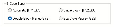
G-Code Type
In this section of the dialog you are telling the CNC machine which threading commands you want to use when posting the G-Code for cutting the 2½ – 8 NPT external thread. The supported commands include the G76 automatic cycle, the G76 double block cycle (specifically designed for Fanuc controllers), the G32/G33 single block and the G92 box cycle. Each of these are discussed below.
Automatic (G71 / G76)
When you need to cut screw threads on a CNC lathe, whether it’s on the inside or outside of a part, the machine uses a special command called G76. Think of G76 as a smart, automated program for threading.
Instead of manually telling the machine to cut a little bit, move back, cut a little more, and so on, G76 handles all of that. You just tell the machine what kind of thread you want – how deep it should be, if it’s a straight thread or taped, and how many times the tool should pass over the material to get to the final depth of the thread.
The machine then works its magic by precisely matching the rotation of the part with how fast the cutting tool moves along the part’s length. This synchronized movement is what creates the perfect spiral of a thread. It’s designed to be very precise and customizable, making complex thread cutting much simpler for the operator.
Double Block (Fanuc G76)
The G76 threading cycle on Fanuc-controlled CNC lathes is a canned cycle that automates multi-pass threading (straight or tapered) using a two-line (double-block) format for precise control over thread cutting.
The First Block is the roughing pass. It specifies pass count, chamfering, tool angle, minimum cut depth, and finishing allowance while the second block is the finishing pass. It defines thread geometry (diameter, length, depth, first pass depth, and pitch).
Single Block (G32 / G33)
G32 and G33 are distinct from G76 (see above) because they are single-pass (i.e., Single Block) threading commands. Instead of automating the entire process, you’re essentially guiding the machine for each individual cut the thread insert makes.
With G32 (and similarly G33), the parameters in the dialog tell the machine precisely where to execute one specific cut from the Start point to the End point on the 2D profile. Using Thread Pitch (P), which is how far the thread advances for every full rotation of the workpiece, the CNC machine perfectly synchronizes the spinning of the part with the cutting tool’s movement to achieve the exact spiral cut.
G32 and G33 are nearly identical on Fanuc controllers. G33 also cuts the thread in one pass but also supports rigid tapping or variable pitch threads on controllers other than Fanuc.
Box Cycle Passes (G92)
The G92 threading cycle is sometimes called a “box cycle” due to its repetitive, box-like toolpath) used for cutting threads. Unlike G76 (a multi-pass canned cycle) or G32/G33 (single-pass threading commands mentioned previously, G92 is a simpler threading cycle that cuts threads in a series of passes at a fixed depth or with incremental depth adjustments. It’s often used on older CNC controllers or for straightforward threading tasks.
With the G92 command, the threading tool cuts along the Z-axis (thread length), then retracts radially (in X), and rapidly returns to the start. This “box cycle” repeats, with each pass going to the same or a deeper X-depth, until the thread is complete. All these repetitions are managed by a single G92 command based on the depth settings entered into the dialog.
In-Feed Type
This portion of the dialog allows you to control how the cutting tool is fed into the material to form the finished thread. You can refer to the dialog illustrations below.
")
The G-Code Type in the Thread Cut Params tab of the Turn Thread dialog set to Double Block (Fanuc G76)
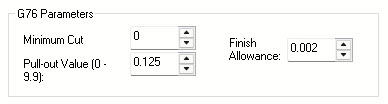
G76 Parameters
The following parameters in this section of the dialog further specify the Automatic G76 thread cycle. The Minimum Cut controls the minimum amount allowance that controls how deep the thread insert can cut. The Pull-out Value determines the amount of chamfering when the cutter retracts on the end of the thread. The Finish Allowance is amount of material left before the final finishing pass.
Cut Material Simulation
With our threading parameters complete its now time to simulate and see our 2½ – 8 NPT external tapered thread.
Post-processing
With our thread generated and simulated, its time to see what the G-Code looks like for a 2½ – 8 NPT External Thread. Below is the G-Code for each thread type.
Automatic G71 / G76 Posted G-Code Sample
")
The G-Code Type in the Thread Cut Params tab of the Turn Thread dialog set to Automatic (G71 / G76)

The G-Code created with the TURN Fanuc Post-processor for the 2½ – 8 NPT External Thread
Double Block (Fanuc G76) Posted G-Code Sample
")
The G-Code Type in the Thread Cut Params tab of the Turn Thread dialog set to Double Block (Fanuc G76)
 G-Code for the 2½ – 8 NPT External Thread")
Double Block (Fanuc G76) G-Code for the 2½ – 8 NPT External Thread
Single Block (G32 / G33) Posted G-Code Sample
")
The G-Code Type in the Thread Cut Params tab of the Turn Thread dialog set to Single Block (G32 / G33)
 G-Code for the 2½ – 8 NPT External Thread")
Single Block (G32 / G33) G-Code for the 2½ – 8 NPT External Thread
Box Cycle Passes (G92) Posted G-Code Sample
")
The G-Code Type in the Thread Cut Params tab of the Turn Thread dialog set to Box Cycle Passes (G92)
 G-Code for the 2½ – 8 NPT External Thread")
Box Cycle Passes(G92) G-Code for the 2½ – 8 NPT External Thread