 What is important to note here is that the control geometry available for defining each machining operations is 2-dimensional. No 3D model yet exists for this prototype. We mention this to illustrate how prismatic parts can be CAM programmed using a 2D drawing and stock dimensions. Let’s have a closer look at how this is accomplished.
Contents
Understand Your Cut Levels (Very Important)
Cut Depth Control (Very Important)
0.125” Center Drill (#1, #2 and #3)
Watch the Cut Material Simulation Video!
About the CAD Drawing
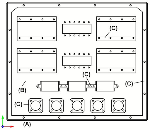
In the 2D drawing below used for machining, there are three cut levels marked (A), (B) and (C). The cross-section drawing shown below is only used for illustrating each cut level. The actual part dimensions are in a the 2D drawing. As the CAM programmer, understanding the depths of these cut levels is extremely important.
Here we see the 2D drawing of the instrument panel. The MCS (Machine Coordinate System) triad is located at the bottom-left corner of the stock. The stock itself is not shown.
Understand Your Cut Levels (Very Important)
The three cut levels (A) Z0.00, (B) Z-0.0545 and (C) Z-0.173 are measured from the top of the ⅜” sheet stock which is at Z0.00. The elevation for each cut level is defined by each machining operation. There are also holes on each of these three levels. These holes are marked Holes (#1), Holes (#2) and Holes (#3). These holes have a Center Drill operation, a Standard Drill operation and Clockwise Tap operations. You can refer to the illustrations for each of these operations below.
. The stock is 0.375” thick. There are a total of three cut levels. These are marked as (A), (B) and (C).")
Above we see a 2D elevation drawing illustrating the finished part (after machining). The stock is 0.375” thick. There are a total of three cut levels. These are marked as (A), (B) and (C).
When you only have a 2D drawing, take a few moments to hand sketch on a pad of paper, the cut levels that the part requires. Taking time to do this before you begin, will help you understand your cut depths. |
The Location of the MCS
Note that the MCS (Machine Coordinate System) is located at the top of the stock and that all cut depth values extend in the -Z (negative Z) direction.
Alternatively, the MCS (Machine Coordinate System) can also be set to the bottom of the stock. In this case, in each machining operation, VisualCAD/CAM (or RhinoCAM) allows you to set the top of each cut.
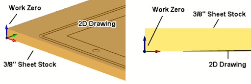
The illustrations below show the 0.375” thick sheet stock, the location of the Work Zero and the location of the 2D drawing. Alternatively, the 2D drawing and Work Zero could be located at the bottom of the stock. These locations will determine what elevation and cut level parameters you enter in each machining operation.
MCS Option 1
In this option (shown below) we see the alignment of the stock and 2D drawing such that the Work Zero and the 2D drawing are elevated to the top of the sheet stock and all Pick Top values for the Location of Cut Geometry would be negative (-Z) coordinate values. Note that Cut Depth values you enter will always be positive and that VisualCAD/CAM (and RhinoCAM) understands this. Also, since the cutting directions on all 3 Axis CNC machines are in the negative Z direction, this option does make sense.

Above we see the Stock, the 2D Drawing and the Work Zero and where they are in relation to eachother.
MCS Option 2
In this option (illustrated below) we see the alignment of the stock and 2D drawing such that the Work Zero is ON the router bed and at the bottom left corner of the sheet stock. This point is also the default zero location of the CNC router. Note that the Cut Depth values you enter will always be positive numbers.
Box Stock and Part Alignment
The Box Stock and Align Part Geometry dialogs for (Option 1) are shown below. The Stock dimensions are 23” x 20” x 0.375”. The Z Alignment is set to Top and the 2D drawing is also located at the top of the stock. Note that all Cut Depth values you enter will always be positive numbers.
The Work Zero
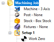
In the Machining Job tree (at right), the location of the Work Zero in is critical. The Work Zero must be located directly below Setup 1 so that all coordinate values in all machining operations under Setup 1 are measured from this Work Zero location. We mentioned above that the Work Zero for Option 1 is located at the top of the Stock. The Work Zero dialog and illustrations below show the required parameters.
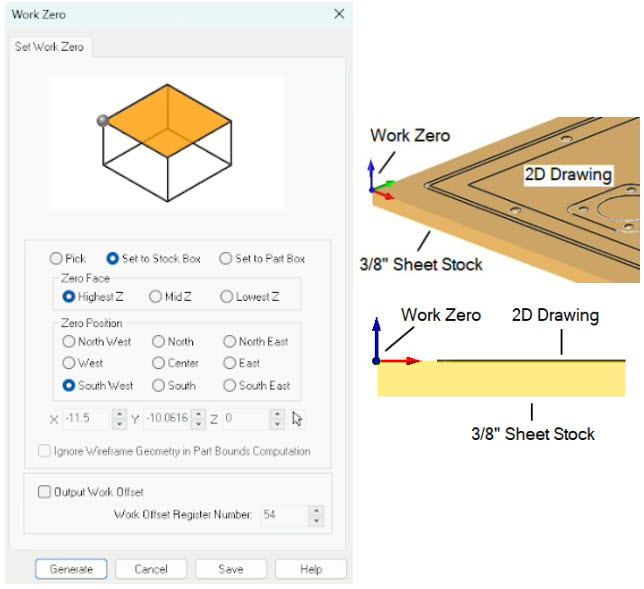
To facilitate the desired Part and Stock relationship, the Work Zero dialog (Left) will need the following parameters. Refer to the illustrations above:
The Work Zero is: Set to Stock Box
The Zero Face is; Highest Z
The Zero Position is: South West
Cut Depth Control (Very Important)
Cut Depth Control is extremely important when you are programming toolpaths with only a 2D drawing. In the table below, each 2½ Axis and Hole Making operation is listed with its Location of Cut Geometry, Pick Top Value and Total Cut Depth. These are the names of the parameters you will see in the Cut Parameters tab of each operation dialog.
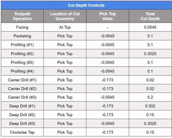
2½ Axis Facing
The first toolpath operation in the machining job will face down the top of the sheet using a 2½ Facing operation and a 2” diameter Face Mill cutter. An island cut pattern is used with a 40% Stepover. The Location of Cut geometry is set to At Top. With the Total Cut Depth set to one pass at 0.0545” and the finished stock thickness will be 0.3205” upon completion. Refer to the Cut Depth Controls chart above.
 Cut Material Simulation (Right)")
2½ Axis Facing: Top view (Left) Cut Material Simulation (Right)
2½ Axis Pocketing
The second toolpath operation in the machining job will pocket the outer perimeter using a 2½ Axis Pocketing operation and a 0.5” diameter Flat Mill cutter. An Offset Cut pattern, Mixed Cut Direction and a Stepover of 25% is defined. For the Cut Levels, the Location of Cut Geometry is set to Pick Top with the top of the cut set to -0.0545” (this is the top of the stock after the previous Facing operation). The Total Cut Depth is 0.1” and is completed in one cut level. There will be 0.025” remaining on the side walls. The entry is a Ramp motion with a linear exit. Again, refer to the Cut Depth Controls chart above.
 Cut Material Simulation (Right)")
2½ Axis Pocketing: Top view (Left) Cut Material Simulation (Right)
2½ Axis Profiling (#1)
The third operation in the machining job will be the first (#1) of 4 profiling operations. It cuts the outer perimeter of the above pocket using the same 0.5”diameter Flat Mill cutter and a Climb Cut Direction. Again, for Cut levels, the Location of Cut Geometry is set to Pick Top with the top of the cut set to -0.0545” (this is the top of the stock after the previous Facing operation). The Total Cut Depth is 0.1” completed in one cut level. The cutter will Ramp on entry and retract straight up upon exit. Inner and outer Cornering is set to Sharp (i.e., no rolling of the tool at corners). Again, refer to the Cut Depth Controls chart above.
 Cut Material Simulation (Right)")
2½ Axis Profiling: Top view (Left) Cut Material Simulation (Right)
2½ Axis Profiling (#2)
The 2nd Profiling operation (#2) will cut all of the inner and outer perimeters that must be cut all the way down to the base of the stock. The same 0.5” Flat End mill cutter is used. In this operation there are a total of 15 perimeter curves starting on the outside and alternating sides inward. Again, for Cut Levels, the Location of Cut Geometry is set to Pick Top with the top of the cut set to -0.0545” (this is the top of the in-process stock). The Total Cut Depth is 0.3205” completed in 4 cut levels at a 0.1” Ramp entry and Sharp corners are specified. Again, refer to the Cut Depth Controls chart above.
 Cut Material Simulation (Right)")
2½ Axis Profiling: Top view (Left) Cut Material Simulation (Right)
2½ Axis Profiling (#3)
The 3rd profiling operation (#3) will cut each of the 9 blind pockets, again using the 0.5” Flat End mill. You will notice from the illustrations below, that these 2½ Axis Profiling operations have a Total Cut Width of 0.3” with a Step/Cut set to 0.1. This means that there will be 3 offset profile passes until the cutter reaches the final perimeter. Again, the Location of Cut Geometry is set to Pick Top with the top of the cut set to -0.0545” (this is the top of the in-process stock). The Total Cut Depth is 0.1” completed in one cut level. The cutter will Ramp on entry and retract straight up upon exit. Again, refer to the Cut Depth Controls chart above.
 Cut Material Simulation (Right)")
2½ Axis Profiling: Top view (Left) Cut Material Simulation (Right)
2½ Axis Profiling (#4)
The 4th profiling operation (#4) will cut the 3 connected pockets, this time using the 0.25” Flat End mill. You will notice from the illustrations below, that this 2½ Axis Profiling operation has a Total Cut Width of 0.2” and with a Step/Cut set to 0.1. This means that there will be 3 offset profile passes until the cutter reaches the final perimeter. Again, the Location of Cut Geometry is set to Pick Top with the top of the cut set to -0.0545” (this is the top of the in-process stock). The Total Cut Depth is 0.1” completed in one cut level. The cutter will Ramp on entry and retract straight up upon exit. Again, refer to the Cut Depth Controls chart above.
 Cut Material Simulation (Right)")
2½ Axis Profiling: Top view (Left) Cut Material Simulation (Right)
0.125” Center Drill (#1, #2 and #3)
Next come the 3 Center Drill operations to prep the cutting of each of the total of 74 drilling operations. Each of these operations are nearly the same except that some have a Pick Top set to -0.173” and the others at -0.0545”. The tip of the diameter drill will cut a depth of 0.02 for all holes. The holes are also sorted based on the Minimum Distance between adjacent holes. Again, refer to the Cut Depth Controls chart above.
 Cut Material Simulation (Right)")
Center Drilling: Top view (Left) Cut Material Simulation (Right)
0.250” Deep Drill (#1)
Next come the 3 Deep Drill operations to finish cutting each of the total of 74 holes. Each of these operations are nearly the same except that 3 different Drill diameters are used, 0.25” diameter, 0.1875” diameter and a #10 Tap Drill. The Location of Cut Geometry and Pick Top values are the same as the Center Drill operations above. In these Deep Drill operations, the cut depth is broken up into peck increments of 0.1. The Drill tool will peck down until it reaches the thru-depth at the bottom of the sheet stock. The holes are also sorted based on the Minimum Distance between adjacent holes. Again, refer to the Cut Depth Controls chart above.
 Cut Material Simulation (Right)")
0.188” Deep Drilling: Top View (Left) Cut Material Simulation (Right)
0.1389” Clockwise Tap (#2)
62 of the holes need to be tapped using a #10-24 Clockwise (right-hand) tapping tool. These tapped holes are labeled (#2) in the illustrations above. The Location of Cut Geometry and Pick Top value for all of these holes is set to -0.173”. The holes are also sorted based on the Minimum Distance between adjacent holes. Again, refer to the Cut Depth Controls chart above.
 Cut Material Simulation (Right)")
Tap Drilling: Top view (Left) Cut Material Simulation (Right)
Cool! We’re glad you stayed with us to the end! It is important to note that this project is for a prototype instrument panel machined from a single aluminum sheet. Here is the completed cut material simulation video.