 In the competitive world of CNC machining, the difference between a good part and a professional-grade part often lies in the finishing. Edge breaking and Deburring are essential for safety, aesthetics, and assembly, yet these tasks are frequently performed by hand or require complex manual programming.
Contents:
Watch the webinar segment here!
The Evolution of Edge Breaking: Why Auto Deburring?
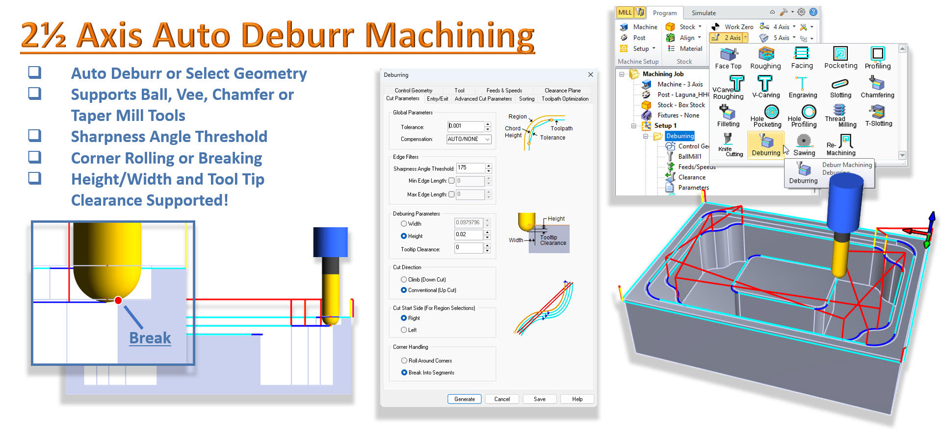
Key Features of Auto Deburring
1. Automatic Edge Analysis (No Geometry Selection)
3. Fully Automatic Gouge Checking
Programming the Operation: Step-by-Step
Step 6: Simulation and Verification
10 Tips for Successful Auto Deburring
Frequently Asked Questions: 2½ Axis Auto Deburring
1. Can I use a standard flat end mill for the Auto Deburring operation?
2. Why is the software skipping some of the edges on my part?
3. Does Auto Deburring work on 3D models or just 2D wireframe?
4. How do I control how much material is removed during Deburring?
5. Does this operation support "Avoidance Regions"?
Introduction
MecSoft has addressed this challenge head-on with the introduction of 2½ Axis Auto Deburring in the latest versions of RhinoCAM and VisualCAD/CAM. This innovative feature automates the tedious process of edge breaking, providing a smarter, safer, and more flexible way to finish your parts.
Based on our recent webinar, this guide explores how the Auto Deburring operation works, why it surpasses traditional Chamfering methods, and how you can implement it in your workflow to save hours of shop time.
Watch the webinar segment here!
Watch the full webinar segment here: Watch the Webinar Segment!
The Evolution of Edge Breaking: Why Auto Deburring?
Historically, if you wanted to break an edge in a CAM environment, you reached for the Chamfering operation. While effective, Chamfering has strict limitations. It typically requires specific geometry selection and, more importantly, a specialized tool like a V-mill or a chamfer mill.
As highlighted in the webinar, the 2½ Axis Auto Deburring operation changes the game by decoupling the edge-breaking process from specialized tooling.
The Power of the Ball Mill
The standout feature of this new operation is its support for standard ball end mills.
•No Special Tooling Required: You no longer need to keep a dedicated chamfer mill in your tool changer for basic edge breaking. If you already have a ball mill in the spindle from a previous finishing pass, you can use it to deburr the part immediately.
•Flexibility: While it supports ball mills, the operation also works with chamfer mills, V-mills, and tapered tools, giving you full control over your tool crib.
Key Features of Auto Deburring
The Auto Deburring dialog may look familiar to those who use the Chamfering operation, but the intelligence under the hood is significantly advanced.

Dialog Box: 2½ Axis Deburring
1. Automatic Edge Analysis (No Geometry Selection)
One of the most time-consuming parts of CAM programming is selecting every individual edge that needs a break. In the Auto Deburring operation, you can leave the Control Geometry tab completely empty.
•Analyze and Execute: When no geometry is selected, the software automatically analyzes the entire 3D part model to locate all sharp edges that are physically accessible by the selected tool.
•Selective Deburring: If you only want to deburr specific areas, you still have the option to manually select edges, providing a balance between total automation and granular control.
2. Sharpness Angle Threshold
Not every edge is a perfect 90-degree corner. Modern parts often feature complex intersecting planes.
•The software allows you to adjust the Sharpness Angle Threshold. For instance, if you have an obtuse edge at 135°, you can adjust the threshold to ensure the software identifies and deburr that edge alongside your standard 90° corners.
3. Fully Automatic Gouge Checking
This is the "intelligence" that makes Auto Deburring a professional-grade tool. When using the automatic method, the software performs a full gouge check against the part geometry, fixtures, and avoidance regions.
•Collision Avoidance: If a ball mill is too large to reach a specific edge without gouging an adjacent wall, the software will automatically skip that edge.
•Safety First: You don't have to worry about the tool "plowing" into the part. If the tool can't safely fit, the toolpath simply isn't generated for that specific segment.
Basic Summary of Workflow
1.Load your 3D Model.
2.Select the Deburring Operation from the 2-Axis menu.
3.Select a Ball Mill (or specialized chamfer tool).
4.Skip Geometry Selection to allow for full automation.
5.Set your Edge Break Height (e.g., 0.020").
6.Generate and Simulate to verify all desired edges are reached safely.
Programming the Operation: Step-by-Step
Setting up an Auto Deburring operation in RhinoCAM or VisualCAD/CAM is remarkably straightforward.
Step 1: Select the Operation
From the program tab, navigate to the 2-Axis menu and select Deburring.

2½ Axis Deburring Menu Item
Step 2: Decide Your Control
For full auto deburr, leave the Control geometry tab empty. Do not select any machining regions. Auto deburr will analyze your part and automatically deburr the edges that the active tool can safely reach without gouging your part.

Dialog Box: Control Geometry tab, Deburring, 2 Axis
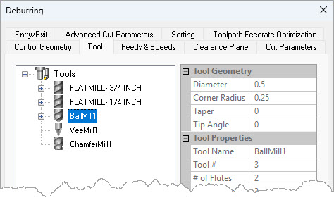
Step 3: Choose Your Tool
Select a ball mill (or a chamfer/V-mill). As seen in the demonstration, using a standard ball mill is often the most efficient choice for general edge breaking.
Step 4: Define Cut Parameters
The Cut Parameters tab of the 2½ Axis Deburr dialog allows you to set the "size" of the edge break.
•Location of Tool on Edge: You can specify the width or height of the break. A common "edge break" is roughly 0.010" to 0.020" (0.25mm to 0.5mm).
•Tool Tip Clearance: Similar to Chamfering, you can drop the tip of the ball mill slightly below the edge to ensure the cut is performed by the side of the ball rather than the very tip (where surface footage is zero).
•Other parameters are similar to the Chamfer operation.
Dialog Box: 2½ Axis Deburring
Step 5: Generate and Simulate
Because there is no geometry selection required, you can simply click Generate. The software will calculate the toolpaths for every accessible sharp edge on the part.
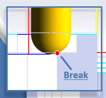
Step 6: Simulation and Verification
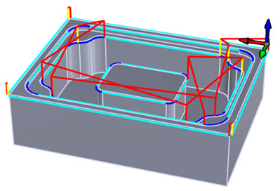
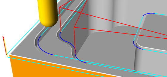
When simulating Auto Deburring, it is recommended to use Polygonal simulation mode to see the fine detail of the edge break. In the webinar, the simulation clearly shows the ball mill tracing the sharp corners of the part, leaving a clean, uniform break. Look at the beautiful corner breaks in the simulation below using only a standard ball mill!
If you notice an edge was not debarred during simulation, it is usually due to the gouge-checking logic mentioned earlier.
•The Fix: If an edge is skipped, try a smaller diameter ball mill. The software will detect the increased clearance and generate the toolpath for that previously inaccessible area.
10 Tips for Successful Auto Deburring
To get the most out of this new functionality, keep these 10 tips in mind:
1.Trust the Automation: Start with no geometry selected. Let the software find the edges for you first, then refine if necessary.
2.Re purpose Ball Mills: Use the same ball mill for finishing and Deburring to minimize tool changes and reduce cycle time.
3.Adjust the Threshold for Chamfers: If your part has pre-modeled Chamfers, use the Angle Threshold to ensure the software recognizes the top and bottom of those Chamfers as edges to be broken.
4.Use Tool Tip Clearance: Always drop the tool tip slightly (e.g., 0.020") to move the cut away from the center of the ball mill for a better surface finish.
5.Honor Your Fixtures: Ensure your clamps and vises are modeled, defined as Fixtures and then assigned to the Setup under which the Deburr operation resides. The Auto Deburring operation will automatically stay away from them.
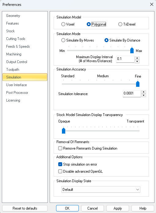
6.Set High Resolution for Simulation: Because deburring is a "fine" operation, set your simulation model to Polygonal and your simulation Accuract to Fine or enter a Simulation Tolerance of 0.0001 to see the results clearly.
7.Check Small Internal Radii: If your tool is larger than an internal corner radius, the software will skip that corner to avoid a gouge.
8.Combine with 3-Axis Work: Even though this is in the 2-axis menu, it works perfectly on 3-axis parts by analyzing the 3D model geometry.
9.Use Avoidance Regions: If there is a specific edge you want to keep "razor sharp" for functional reasons, select it as an avoidance region.
10.Analyze the Cut Heights: If you want a heavier "look" to your edge break, use a larger height value (e.g., 0.030") to create a more visible chamfer-like effect with the ball mill.
Conclusion
2½ Axis Auto Deburring represents a significant leap forward in CAM usability. By automating the edge-selection process and allowing for the use of standard ball mills, RhinoCAM and VisualCAD/CAM have made professional-level finishing accessible to every user.
Whether you are looking to save time on the shop floor or simply want a more reliable way to ensure your parts are safe to handle, Auto Deburring is a tool that should be in every programmer's arsenal.
Watch the Webinar Segment!
Watch the full webinar segment here: Watch the Webinar Segment!
Frequently Asked Questions: 2½ Axis Auto Deburring
1. Can I use a standard flat end mill for the Auto Deburring operation?
While the operation supports many tool types, a flat end mill is generally not recommended for deburring unless the edge is specifically oriented to allow for a chamfer-like cut. For the best results with the Auto Deburring logic, use a ball end mill, chamfer mill, or V-mill. The ball mill is the most versatile as it can break edges at various angles and at the same time be in the tool carousel for other 3 Axis finishing operations.
2. Why is the software skipping some of the edges on my part?
This is almost always due to the built-in Automatic Gouge Checking. If the tool you selected is too large to fit into a tight area or would strike a vertical wall while trying to break an edge, RhinoCAM will skip that segment to protect your part. To resolve this, try selecting a smaller diameter ball mill.
3. Does Auto Deburring work on 3D models or just 2D wireframe?
It is designed to work directly on 3D models. By analyzing the surfaces of your part, the software identifies "sharp" intersections. While it is located in the 2-Axis menu, its intelligence comes from its ability to understand the 3D volume of the part, fixtures, and avoidance regions.
4. How do I control how much material is removed during deburr?
In the Cut Parameters tab, you can define the "Edge Break" by either Width or Height. For a standard "break," a value between 0.010" and 0.020" is typical. You can also use the Tool Tip Clearance setting to shift the contact point of the tool for a smoother surface finish.
5. Does this operation support "Avoidance Regions"?
Yes. If you have specific edges that must remain sharp for functional reasons (such as a sealing surface), you can select those edges or surfaces as Avoidance Regions in the Control Geometry tab. The software will calculate the "Auto" paths for everything else while leaving those specific areas untouched.