 Programming a five-axis machine has traditionally been one of the most time-consuming tasks in the CAM office. The process of manually determining orientations, creating indexed setups, and defining individual toolpaths for every side of a complex part is a meticulous endeavor that leaves plenty of room for human error.
Contents
•What is 3+2 (Indexed) 5-Axis Machining?
•The Power of Auto-Roughing: Intelligent Analysis
•Flexibility for the Programmer
•Real-World Application: Multi-Sided Roughing
•Efficiency Through Automation
•The Future of CAM: Your Input Matters
•Watch the full 5-Axis Auto-Roughing demonstration
Introduction
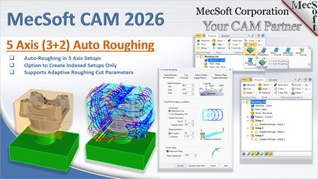
In our latest webinar, MecSoft Corporation showcased a significant breakthrough in automation: 5-Axis 3+2 Auto-Roughing. This new feature, debuting in the 2026 version of VisualCAD/CAM, is designed to take the "manual" out of multi-sided machining.
What is 3+2 (Indexed) 5-Axis Machining?
Before diving into automation, it’s important to clarify the technology. 3+2 machining, also known as Indexed 5-Axis, involves using a five-axis machine tool to position the part at a specific orientation (the "plus Z" axes) and then locking those axes in place while the 3 primary axes (X, Y, and Z) perform the cutting.
This allows you to machine features from different sides of a part without having to manually unclamp and flip the workpiece. However, the setup work in the software—deciding exactly which angles are best and creating setups for each—has always been a bottleneck.
The Power of Auto-Roughing: Intelligent Analysis
The new 5-Axis Auto-Roughing operation changes the workflow from a series of manual decisions to an automated analysis.
How it Works
•Geometric Analysis: The software automatically analyzes your part model against the stock model.
•Zero-Geometry Selection: Unlike traditional methods, you don't have to select "control geometry." The system "looks" at the part and the surrounding stock to understand where material needs to be removed.
•Automatic Setup Creation: It determines the best orientations to approach the part from and creates the corresponding setups in the machining job tree automatically.
•Adaptive Toolpath Generation: It then populates those setups with 3 Axis Adaptive Roughing toolpaths—high-efficiency paths that maintain a constant tool load and allow for faster material removal.
Flexibility for the Programmer
While the "Auto" in Auto-Roughing implies the software does the heavy lifting, the programmer remains in control.
•Generate Setups Only: You have the option to let the software calculate and create the setups (orientations) without generating the toolpaths immediately, allowing you to add your own specific operations later.
•Familiar Interface: The parameters within the Auto-Roughing dialogue are identical to the standard Adaptive Roughing dialogue you already know, covering horizontal and adaptive cut parameters.
Real-World Application: Multi-Sided Roughing
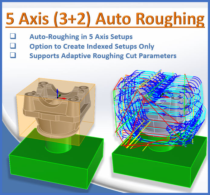
In the webinar demonstration, we looked at a complex part mounted on a pedestal—a common setup that allows a 5-axis spindle to reach nearly every face of the stock.

Sample Geometry for 5 Axis Auto-Roughing
You can locate the Auto-Rough operation on the 5 Axis menu on the Program tab shown below.

You can locate the Auto-Rough operation on the 5 Axis menu on the Program tab

By default, the Axis Control tab of the 5 Axis Auto-Rough operation is displayed first.
You can accept the default parameters or set the following parameters:
•Start Tool Axis: This allows you to set a preferred starting direction. The operation begins machining from this direction, then continues searching for any remaining areas not yet machined.
•Search Angle Increment: This allows you to define the angular increment in which the operation will look for indexed 3+2 orientations to machine. For example, if Start Tool Axis is set to +Z and this parameter is set to 90, only orthographic directions will be machined.
•Max Stock to Leave: The operation stops looking for additional machining orientations when this amount of stock is left in relation to the part. This prevents generating setups for negligible remnants of material.
•Max Tilt Angle: This controls the Max Tilt Angle of the tool axis for each cut direction. The angle is measured normal (i.e., perpendicular to) the Setup's XY plane for each calculated iteration. The default value of 90 means that the spindle axis is normal (i.e., perpendicular) to the Setup XY plane.
•Limit Height: You can define the maximum height of stock in relation to the active tool. It can be set to the tool’s flute length or a user specified value.
•Generate Setups Only: If you want more direct control, choose this option and only the setups are generated, leaving you to program each setup according to your machining standards.
When you pick the Generate button, the software instantly analyzes the geometry and creates the following three setups based on the Axis Control parameters shown in the Axis Control dialog above.
•Setup 1: Top-down approach (Adaptive Rough - Setup 1)
•Setup 2: Front-side approach (Adaptive Rough - Setup 2)
•Setup 3: Left-side approach (Adaptive Rough - Setup 3)

When you pick the Generate button, the software instantly analyzes the geometry and creates the three setups based on the Axis Control parameters shown in the Axis Control dialog above.
Instead of a programmer manually calculating these angles and creating three separate machining operations, the software handled the logic in one step. This ensures that the bulk of the material is cleared out efficiently, leaving the part ready for semi-finishing and finishing operations.

Indexed 3 Axis Adaptive Roughing operations are automatically created for each automated Setup
Efficiency Through Automation
The primary goal of this feature is time savings. By automating the initial roughing phase—which is often the most repetitive part of programming—you can move from a raw CAD model to a simulated rough-cut part in a fraction of the time.
When paired with the NVIDIA GPU-Accelerated TriDexel Simulation (also showcased in the 2026 release), you can calculate these complex multi-sided toolpaths and simulate them almost instantly, creating a rapid, iterative workflow that was previously done manually, in the case of 5 Axis Setups and Adaptive Roughing and more time consuming, in the case of cut material simulation.
Key Features Summary
•No Control Geometry Needed: Just part and stock.
•Automatic Setup Logic: The software finds the best angles.
•High-Efficiency Paths: Uses Adaptive Roughing technology.
•Speed: Reduces programming time by automating repetitive setup tasks.
The Future of CAM: Your Input Matters
At MecSoft, our theme for 2026 is Automation to make your job easier. The 5-Axis Auto-Roughing feature is a "work in progress" in the sense that we are looking for user feedback to refine how the software chooses its approach angles and handles different stock shapes. We encourage your feedback. You can reach us at support@mecsoft.com.
If you are currently machining five-axis parts or looking to transition into indexed 5-axis work, this tool is designed to lower the barrier to entry and maximize your machine's uptime.
Watch the full 5-Axis Auto-Roughing demonstration here: https://youtu.be/JbaHFDZICx8