 The chosen parts for this article are the Drawer Pulls on the Dresser design shown below submitted by Curtis Erpelding, Proprietor or Erpelding Furniture located in Port Orchard Washington. The dresser is made of European Pearwood. It is 72 inches wide, 22 inches deep and 36 inches high. It is composed of 11 drawers, 4 on each side and 3 in the middle. Each drawer has identical Drawer Pulls, 11 total. The Drawer Pull design is unique in that it consists of a curved undercut pocket shown in the illustrations below.
Read the full case study here
Contents
The CAD/CAM Part
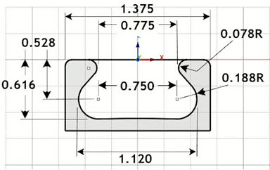
Here we see the width section view of the Drawer Pull showing the dimensions of the undercut. The part is 1.375” wide and 0.676: High.
 – Erpelding Furniture")
European Pearwood dresser with drawer pull design (inset) – Erpelding Furniture
The length section of the Drawer Pull, shows that the top of the part and the bottom of the pull pocket are cut on a radius of 96.00” and 71.50” respectively. The arc at the base of the pocket requires special attention. This is not a simple flat-bottom pocket.

Here we see the Length section view of the Drawer Pull. As noted, the top of the part and the bottom of the pocket are cut on an arc. It is a very unique design that requires some very unique machining operations.
The Cutting Tools
The Machining Job for this project will require three Carbide cutting tools. They are shown below listed in the Tools tab of the Machining Objects Browser (left side image). Two are standard tools, 1⁄4” Flat End Mill and ¼” Ball End Mill. The third is a custom tool. Custom tools, also referred to as Form Tools, can be defined by drawing the tool profile and then using the Custom Tool definition from the Create/Select Tools dialog.

Here we see the list of tools for this Machining job. From left to right, we have the list of tools used, followed by a 1⁄4” diameter Flat End Mill, a ¼” diameter Ball End Mill and the Custom Form Tool on the right. You will note that the profile of the custom form tool matches the profile of the undercut required by the Drawer Pull design.
The Machining Job
Based on the part features described above, the following toolpath operations are used to machine this part. You will notice from the Machining Job shown below that there are seven 2 axis Engraving operations. These are the paths needed to machine the undercut. The Engraving operations 1 thru 6 are considered roughing passes while the 7th and final path is the finishing.

The Machining Job shown above consists of one Setup containing 2 axis and 3 axis roughing and finishing operations.
You will also notice from the Machining Job that the first operation is 2 axis pocketing. This serves as the roughing path to remove the bulk of material from the undercut pocket. The three 2 axis profiling operations rough and finish the perimeter of the part. The last 3 axis Parallel Finishing operation cuts the top of the part across the 96” radius.
2½ Axis Pocketing (Roughing)
This initial Pocketing operation is a roughing operation that uses a ¼” diameter Carbide Flat End Mill and cuts in 7 cut levels, each approximately ⅛” deep for a total depth of 0.54”. The cutter enters on a 10 degree ramp entry, Arc Fitting is enabled and the in-process Stock Allowance is 0.025”. You can refer to the illustrations below,

The first operation is 2 Axis Pocketing and serves as the first roughing operation.
2½ Axis Profiling (Roughing)
Next in the Machining Job are 3 consecutive 2 Axis Profiling operations to rough and finish the outer perimeter of the part using the same Carbide Flat End Mill. The first Profile cuts in 5 cut levels, each at 0.135” deep. This first Profile is a roughing operation leaving 0.02” of stock. You will also notice that all three Profiling operations have automatic Bridges and Tabs enabled with one tab on each side of the part. These tabs will serve to anchor the part to the remaining stock during machining and will be removed manually.

Here we see the first 2 Axis Profiling operations with multiple cut levels.
2½ Axis Profiling (Finishing)
The second and third Profiling operations are identical except for the direction of cut. The second operation uses a Climb (down cut) direction while the 3rd uses a Conventional (Up Cut) direction. Both operations have a 3 degree Ramp Entry (shown in magenta in the images below). Again, automatic Bridges and Tabs enabled are enabled with the same parameters as the first profiling operation.

Here we see the third 2 Axis Profiling operations. This is the finish pass for the perimeter of the part. The 3 degree ramp entry is shown in magenta.
2½ Axis Engraving (Roughing)
The next seven operations in the Machining Job are all 2 Axis Engraving paths. During Engraving, the tip of the Custom Tool cutter will follow a predefined curve region. This provides the exact control needed to cut the undercut pocket. Each of the first 6 Engraving operations are considered roughing passes.

Here we see the Custom Tool profile cutter rough machining the undercut pocket. The toolpath is at the tip of the cutter.
2½ Axis Engraving (Finishing)
The last Engraving operation is considered the finishing path. The cutter profile is used to form each side of the pocket. While the previous 6 Engraving operations cut flat horizontal passes, for this final Engraving operation, the pre-defined curve region follows the exact curvature at the base of the undercut pocket.

Here we see the final finishing cut across the top 96” radius of the part.
The Final Part Simulated
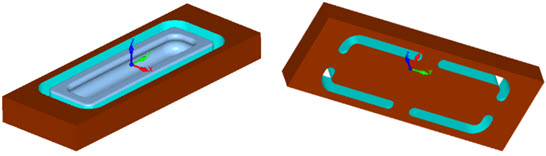
Below you can see the cut material simulation results after all operations in the Machining Job are simulated. You can clearly see the tabs that were left behind serving to keep the part attached to the stock during machining.
Cutting Multiple Copies
In this article we show how one part is programmed. Curtis needs 14 identical Drawer Pulls. He can do this easily using VisualCAD/CAM’s XY Instancing feature. He will need 3 copies in the Y direction and 2 copies in the -X direction. The dialog and the resulting toolpaths are shown below. To cut all 14 Drawer Pulls at the same time, you can use XY Instancing or even Work Offset registers.

Using the XY Instancing function in VisualCAD/CAM is easy. Just specify the X and Y offsets and the number of copies and the instancing takes place, well instantly!