Note: This blog post is a portion of a larger MecSoft Corporation written case study on the successful implementation of RhinoCAM at Piedmont Composites & Tooling located in Taylorsville, NC. You can read the full case study here.
Note: While this article is written in the MILL Module, the same principles apply to the TURN Module Machining Job.
Contents
Cloning Examples in an Indexed 5 Axis Machining Job
Setup 2: 3 Axis Horizontal Roughing (Master)
Setup 3: Transfer: 2½ Axis Engraving (Master)
Setup 4: 3 Axis Horizontal Roughing (Clone)
Setup 5: Transfer: 2½ Axis Engraving (Clone)
Setup 6: 3 Axis Parallel Finishing (Master)
The Finished Plug Form and Composite Basin
Introduction
In RhinoCAM (or VisualCADCAM) you can save time and maintain consistency by creating a toolpath operation with all of its parameters just once and then “Cloning” the operation for as many times as you need to use it within the Machining Job tree. As you review each of the Setups and toolpath methods in the Machining Job sections below, note that there are only three toolpaths’ methods used. These are 3 Axis Horizontal Roughing, 3 Axis Parallel Finishing and 2½ Axis Engraving.
Each toolpath method is defined once and then cloned as needed throughout the machining Job. The only difference is the set of control geometry that each method is applied to. Additionally, the first instance of a toolpath can be loaded into the Machining Job from a knowledge base of operations tailored specifically to your requirements. This makes the CAM programming in RhinoCAM fast and consistent!
 and then Cloned as needed in the Machining Job tree. Master operations can also be loaded from a Knowledge Base tailored to specific applications.")
Toolpath operations are created once (the Master) and then Cloned as needed in the Machining Job tree. Master operations can also be loaded from a Knowledge Base tailored to specific applications.
The Machining Job
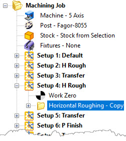
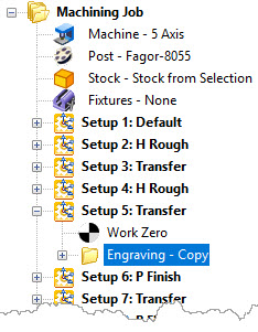
Below you see the entire Machining Job for this part. It consists of 13 individual Indexed 5 Axis Setups. The Setups named Transfer (Setups 3, 5, 7, 9, 11 and 13) are all 2½ Axis Engraving operations cloned from a single source operation that was loaded from a Knowledge Base of operations. Setups 2 and 4 are 3 Axis Horizontal Roughing operations cloned from a single Knowledge Base operation. Setups 6, 8, 10 and 12 are for 3 Axis Horizontal Finishing operations also cloned from a single Knowledge Base operation.

The final 5 Axis Machining Job Tree in RhinoCAM
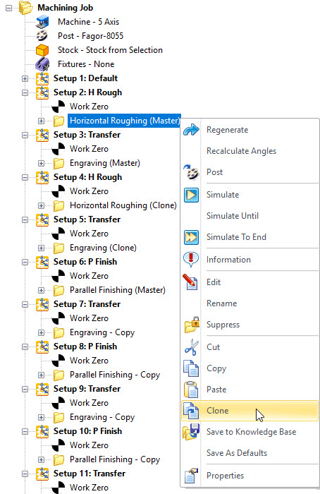
How to Clone an Operation
You can Clone machining operations from the Machining Browser. To Clone an operation, select the operation under the Machining Job treeBrowser, right-click and select Clone. This performs a Copy/Paste on the selected operation. The menu and resulting operation is illustrated below.
Cloning Examples in an Indexed 5 Axis Machining Job
Below is a real-world example using the same Machining Job tree shown above. There are only three machining operations loaded from a Knowledge Base of operations. These are considered Masters. All subsequent operations in the Machining Job example are considered Clones.
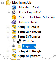
Setup 2: 3 Axis Horizontal Roughing (Master)
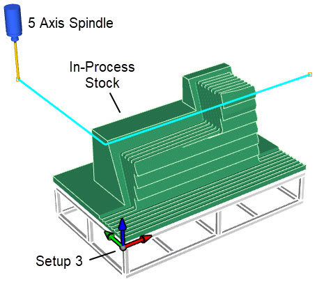
There are two Indexed 3 Axis Horizontal Roughing operations in this Machining Job and Setup 2 contains the first. It is the Master operation from which the second identical operation is cloned. It will rough out the front side of the part in levels. You can follow the illustrations below with the Machining Job tree on the left and the finished in-process stock on the right. In the middle you see the toolpath. The Setup indicates the +Z orientation of the 5 axis spindle and is indicated by the triad and the blue arrow. The location of the 5 Axis spindle is shown at the end of the cut.
Cut Parameters Include: Control geometry: Part & Stock, Tool: 25mm Ball Mill, Cut Tolerance: 0.01”, Stock Allowance: 0.05”, Cut Pattern: Linear, Cut Direction: Mixed, Stepover Distance: 50% (of Tool Diameter), Stepdown: 2”, Cut levels: Top: 1.63” and Bottom Containment: -16.25”, Transfer: Skim 1.5”, Cut Arc Fitting: Enabled, Engage/Retract: Helical.
|
|
|
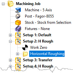

On the left we see the Machining Job with the first 3 Axis Horizontal Roughing operations selected. In the middle we see the +Z orientation of the spindle and the location of the 5 Axis spindle at the end of the cut. On the right we see the resulting simulation and in-process stock once the cut is complete.
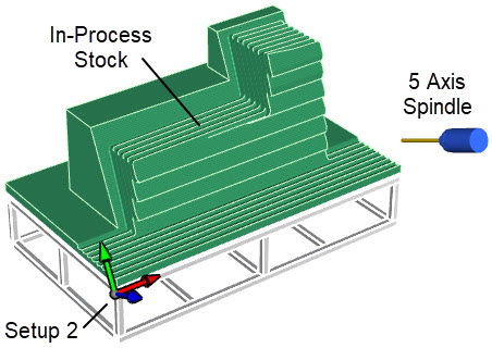
Setup 3: Transfer: 2½ Axis Engraving (Master)
Setup 3 contains the first of six Engraving operations. It is the Master operation from which the 5 identical operations are cloned. This operation will guide the tool to the opposite back side of the part near where the next operation will begin. The illustrations below show the Machining Job tree on the left. In the middle we see that the +Z axis of the Work Zero triad is pointing vertical. The light blue lines are the Control Geometry that the tool will follow, and the 5 Axis spindle is shown at the end of the Engraving operation near the back side of the part. On the right, the simulation of the in-process stock has not changed.
Cut Parameters Include: Control Geometry: XY Planer Lines, Tool: 25mm Ball Mill, Cut Tolerance: 0.001”, Cut depth: 0”, Sorting: Directional, Entry/Exit: None.
|
|
|
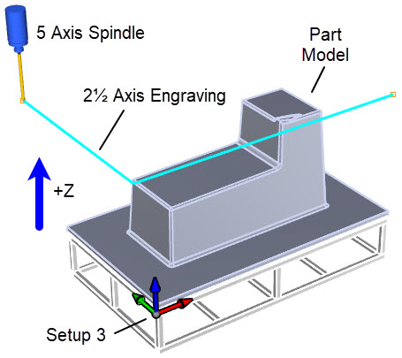
The Machining Job tree is shown on the left. In the middle we see that the +Z axis of the Work Zero triad is pointing vertical. The light blue lines are the Control Geometry that the tool is following, and the 5 Axis spindle is shown at the end of the Engraving operation near the back side of the part. On the right the simulation of the in-process stock has not changed.
Setup 4: 3 Axis Horizontal Roughing (Clone)
Setup 4 contains the cloned 3 Axis Horizontal Roughing operations in this Machining Job. This operation is an exact clone of the Master operation and its parameters in Setup 2. It will rough out the back side of the part in levels. You can follow the illustrations below with the Machining Job tree on the left and the finished in-process stock on the right. In the middle you see the toolpath. Again, the Setup 4 triad indicates the +Z orientation of the spindle and is indicated by the blue arrow. The location of the 5 Axis spindle is at the end of the cut.
|
|
|
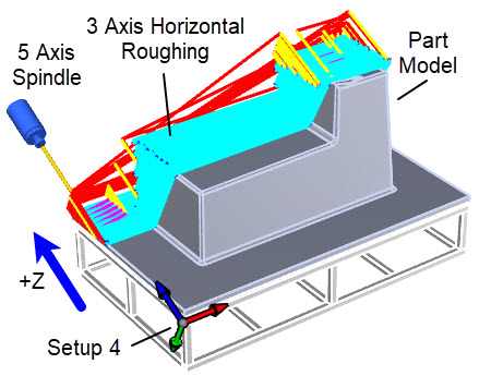
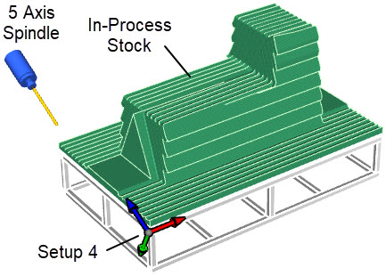
On the left we see the Machining Job tree with the 3 Axis Horizontal Roughing operation selected. The finished in-process stock is on the right, and the toolpath is shown in the middle. Again, the Setup 4 triad indicates the +Z orientation of the spindle and is indicated by the blue arrow and the location of the 5 Axis spindle is at the end of the cut.
Setup 5: Transfer: 2½ Axis Engraving (Clone)
Setup 5 contains the second cloned 2½ Axis Engraving operation. This operation is an exact clone of the master operation and its parameters in Setup 3. This operation will guide the tool to the right side of the part near where the next operation will begin cutting. The illustrations below show the Machining Job tree on the left. In the middle we see that the +Z axis of the Setup 5 triad is again pointing vertical. The light blue lines are the Control Geometry that the tool will follow and that the 5 Axis spindle is shown at the end of the Engraving operation near the back right side of the part where the next cut will begin. On the right, the simulation of the in-process stock again has not changed.
|
|
|
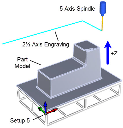
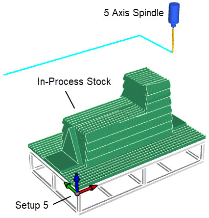
These illustrations show the Machining Job tree on the left with the Engraving operation selected. In the middle, the +Z axis of the Setup 5 triad is pointing vertically and the 5 Axis spindle is shown at the end of the Engraving operation near the right side of the part. On the right, the simulation of the in-process stock again has not changed.
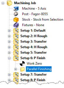
Setup 6: 3 Axis Parallel Finishing (Master)
Setup 6 contains the first of four 3 Axis Parallel Finishing operations. It is the Master operation from which the 3 identical operations are cloned. These four finishing operations will finish the part on each of the part’s four sides. The Setup 6 triad indicates the +Z orientation of the spindle and is indicated by the blue arrow. The location of the 5 Axis spindle is at the end of the cut. The toolpath is shown in the middle image with a very fine stepover. On the right in-process stock image you see that the finishing operation is contained to the orange Control Boundary curves. These curves are actual surface edges of the part model.
Cut Parameters Include: Control Geometry: Closed Surface Edges, Tool: 25mm Ball Mill, Cut Tolerance: 0.001”, Stock Allowance: -0.0625” (Overcut), Cut Direction: Mixed, Stepover Control: 0.05”, Cut Pattern: Linear, Cut Direction: Mixed, Start Side: Bottom, Stepover Control: 0.05”, Z Containment: None, Perform Cut Arc Fitting: Enabled, Entry/Exit: Linear, Cut Connections: Straight.
|
|
|
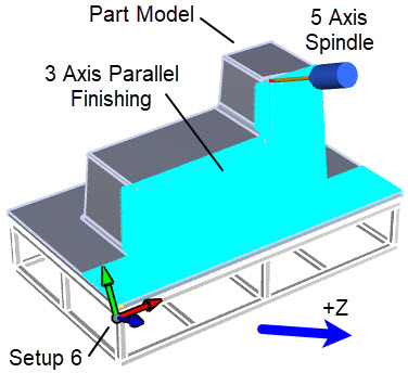
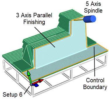
The above illustrations show the Machining Job tree on the left with the first 3 Axis Parallel Finishing operation selected. In the middle we see the +Z orientation of the spindle for Setup 6 and the location of the 5 Axis spindle at the end of the cut. On the right we see the resulting simulation and in-process stock once the cut is complete.
The Finished Plug Form and Composite Basin
The images below show the Baptistery plug form on the left after machining and still sitting on its support fixture in the C.R. Onsrud “LR” (Light Rail) series 5-axis CNC router chamber. The production 60” long x 24” wide x 36” deep composite baptistry basin is shown on the right.
|
|
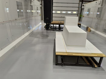
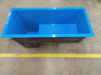
Above we see the Baptistery plug form on the left after machining and still sitting on its support fixture in the C.R. Onsrud “LR” (Light Rail) series 5-axis CNC router chamber. The production 60” long x 24” wide x 36” deep composite baptistry basin is shown on the right.