The subject of this post is the Anjamar, a Custom Carolina 45, flybridge, featured at the Palm Beach Boat Show by Rhodes Yacht Design. The Anjamar is uniquely designed with tremendous thought given to styling performance and function with all the qualities of a custom sportfish powered with the simplicity of outboards. Anjamar was built to the highest of standards using modern technology right down to the carbon fiber bulkheads. Learn more about the full case study here.

The Custom Carolina 45
1. The Parts to NEST
The parts for this case study when assembled form the jig and fixtures upon which the Wheel House of the Custom Carolina 45 yacht is assembled. The assembly consists of 20 interlocking components that are each 2D line drawings that lie on the XY plane. You can see the assembly in the illustrations below.

The components when assembled form the jig and fixtures upon which the Wheel House of the Custom Carolina 45 yacht is assembled.
2. Staging Components for Nesting
In preparation for nesting, each component is moved such that no component is touching or overlapping each other while remaining on the XY plane. Note that optionally, during the nesting process, each component can be projected onto the XY plane. All of the components are also moved outside of the default positive XY quadrant. This is done because the positive XY quadrant is where the actual nesting takes place.
So now our assembly looks like this:

The part components to NEST are staged and ready to begin the NEST process
3. Loading NEST
NEST is a module of RhinoCAM (and VisualCADCAM). It is available to all users who are active Annual Maintenance Subscribers (AMS). To launch the NEST module, load the RhinoCAM plugin for Rhino. Then go to the RhinoCAM main menu and select NEST. This will display the NEST module browser as shown below.

RhinoCAM NEST is loaded from the RhinoCAM Main Menu in Rhino
4. About the NEST Browser
When selecting NEST from the RhinoCAM Main Menu, the Nesting Browser by default will display on the left side of the Rhino display. You can move it by dragging and docking like any other Rhino menu. The NEST Browser consists of a collection of Tabs that will walk you through the process of Nesting. These include the NEST type, the NEST sheets, the NEST parts, the NEST Parameters, the NEST Preview and finally to Commit the NEST.

The NEST Browser contains each tab required to create nested components onto a flat sheet.
5. The Select Type of Nesting Tab
As shown in the image above the Select Type of Nesting tab allows you to select from two types of nesting, True Shape Nesting and Rectangular Nesting. Each is defined below and for this project, the True Shape Nesting option is selected.
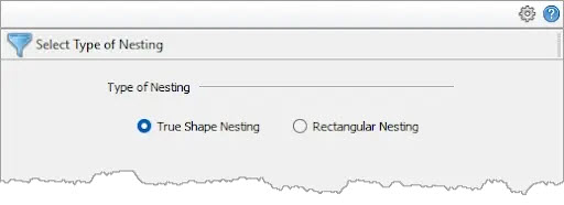
•True Shape Nesting: This method is useful when the actual geometric details of the part are taken into consideration while nesting. True shape nesting enables interlocking of parts, recognition of arbitrary shaped sheets.
•Rectangular Nesting: This method is ideal for nesting mostly square and rectangular profiles. For all part shapes, an imaginary rectangle is drawn around the shape and then the rectangles are then nested.
6. Select Sheets to Nest Parts In
The next tab of the NEST Browser is where you define the size of each sheet and other sheet-related options in the NEST. As we mentioned above the nesting process occurs in the plane of the positive XY quadrant. As shown in the set of buttons below the sheets list, you can Add/Edit Sheet(s) or Select Curve(s). Fior the Select Curve(s) option you need to draw a rectangle whose bottom-left corner is located at the 0,0,0 location and whose sides extend in the direction of the positive X and Y axis quadrants.

Here we see the Select Sheets to Nest Parts in tab of the Nesting Browser
For this project we are using the Add/Edit Sheet(s) button which then displays the additional fields to define the sheet parameters. At this point, we enter values in the Length, Width and Thickness fields, 96, 48 and 0.750 respectively. We will leave the Count set to 1 because we don’t know yet how many sheets are needed and when we do (see step 8 below), it will update automatically! For the Name, and X, Y fields we will accept the default values.
7. Select Part(s) to Nest Tab
This next tab is where we add the parts that we want nested onto the sheets. First, we will pick the Select Part(s) button. We are prompted to select geometry and we window select all of the parts that we have staged and then right-click or press Enter. When we do, we see that all of the parts get added to the table. You will notice from the list that each part has Child cutouts and each cutout is added to the list as a Child under the part they belong to.
 to Nest tab of the Nesting Browser")
Here we see the Select Part(s) to Nest tab of the Nesting Browser
The Orientation Step Angle parameter under the Part Options section, is a constraint that is applied during nesting. It defines how many degrees of freedom each part can rotate in order to complete the nest. We want minimal constraints so we set it to 1. You will notice that each of our parts have interior cutouts so we want to check the box to Preserve Part(s) within Parts relationship. This will make sure that each part and its cutouts are preserved as one part. The parts Count, Priority, Orientation, and Grain Direction are left to their default values. The part to nest (in red) and the nested sheet (blue) are all shown in the illustration below.

Here we see the Parts to Nest in red and the Sheet to Nest Parts on in blue.

Here we see one of the parts in the nest.
Notice that it has a closed perimeter curve and that it has a number of interior cutouts.
One of the parts is shown above. Notice that the perimeter of the part is a closed curve. This is required. Also notice that there are a total of 6 interior cutouts. Also notice that 4 of the cutouts are alpha-numeric characters. For this project this serves to identify the part in the final assembly. “Tagging” can also be done automatically during nesting.
8. Choose Nesting Parameters
Next up is the Choose Nesting Parameters tab that contains most of the parameters that you can adjust to influence the resulting nested sheet(s). We will list these parameters and their values below. Most are self-explanatory:
•Distance Part to Part: 0.5
•Distance Part to Sheet: 0.5
•Tag Height: default value (not used in this project)
•Nested Sheet Layout: Along X
•Spacing between sheets: 1
•Remnant type: Clean Cut (explained below)
•Remnant, Clean Cut Type: Vertical Cuts (Explained below)
•Remnant Size Control: Width (Explained below)
•Remnant Min. Width: 5 (Explained below)

Here we see the Choose Nesting Parameters tab. Notice the section for Remnant Control.
9. Understanding Remnants
In many cases, there will be areas of each nested sheet that are not being used. This can be due to the shape of your parts, how many parts are in the nest and how each part is positioned. RhinoCAM NEST allows you to reuse these sheet remnants. The Remnants section of the Choose Nesting Parameters tab contains all of the options to control your remnant sheets. With Remnants enabled, the unused portions of each sheet can be reused in subsequent nesting jobs.
10. Estimating the Number of Sheets
When all of the nesting parameters are to our liking, we now pick the Estimate Number of Sheets button located at the bottom of the Choose Nesting Parameters tab. RhinoCAM-NEST will perform calculations to estimate the total number of nested sheets we will need. Also, the Estimate # of Sheets dialog below also allows us to automatically update the sheet count displayed on the Select Sheet(s) to Nest Parts in tab (shown in 5. above).
 to Nest Parts in tab (see 5. above)")
The system estimates the total number of sheets needed. You can also update the Count parameter in the Sheet(s) to Nest Parts in tab (see 5. above)
11. Execute the Nest
In this step, all of our parameters from the steps above are taken into account, the NEST is executed and then we are moved automatically to the Preview Nest tab of the NEST Browser.
12. Preview Nest
The Preview Nest tab shows three tables. They are, from top to bottom, List of Nested Sheets, List of Unnested Parts and List of Remnant Sheets. When you select a sheet from the List of Nested Sheets, a preview on that nested sheet is displayed. Because we selected “Along X” from the Nested Sheet Layout section of the Choose Nesting Parameters tab (see 7. above), the nested sheets are previewed one at a time beginning from 0,0,0 and extending along the X axis.
 and the Remnant Sheets (if Remnants are enabled)")
The Preview Nest tab lists the Nested Sheet, Unnested Sheets (if any) and the Remnant Sheets (if Remnants are enabled)

Here we see a preview of all 7 of the nested sheets.
13. List of Remnant Sheets
If you recall, we enabled the Remnants section of the Nesting Parameters tab (see 8. above), and set the Remnant Type to Clean Cut, we set the Clean Cut type to Vertical Cuts, we set the remnant Size Control to Width and the Minimum Width to 5. The Remnants section of the Nesting Parameters tab is shown again below.

Here we see the Remnant parameters we set from the Nesting Parameters tab.
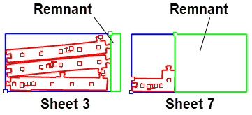
Now, from the Preview Nest tab we see that there are two Remnant Sheets listed in the List of Remnant Sheets. Selecting each Remnant Sheet from the list will poreview that sheet. For better understanding, the preview geometry is color-coded. The sheet perimeter is BLUE, the nested parts are RED and the Remnant is GREEN. This is shown in the illustration below.
14. Nesting Report
From the Preview Nest tab you can select the Report button to see a nesting report. The report lists each sheet in the nest and where in the nested sheets each part is located. The Nesting Report is shown below.

The nesting report shows the sheets where each nested part is located.
15. Committing the Nest
After you have previewed the nest and are sure that it is to your liking, select the Commit Nest tab. The term “Commit Nest” means that once the nest is committed, you cannot undo or change any parameters. To change any parameters, you must start over with the nesting process.

The Commit Nest tab includes parameters for committing the nested sheets to actual geometry that can then be used for other purposes inside Rhino such as generating toolpaths in RhinoCAM.
The parameters on this Commit Nest tab are pretty self-explanatory and we will not go into much detail. We do however, want to discuss the Remnants section of the dialog. Since we have identified 2 sheets with remnant material, we want to decide how those remnants are handled when the nest is committed. By default each remnant will be defined by creating a closed perimeter boundary. The closed perimeter curve geometry of these two remnants will then be added back into the sheets list on the Select Sheets to Nest Parts in tab (see 6. above). We also want each remnant geometry on a separate layer.
16. The Commit Nest Button
OK, all of our nesting parameters are set and now we pick the Commit Nest button. Each nested sheet is converted into actual Rhino geometry. Here is exactly what happens:
1.Each sheet is defined by a closed rectangle.
2.Each nested part geometry is added to its designated sheet.
3.Each sheet is placed side-by-side along the X axis.
4.Layers are created for each nested sheet and each remnant sheet.
5.The two remnant sheets are added to the Sheets list.

Above we see the first three sheets of the committed nest. The first of two remnant sheets are is shown on Sheet #3. The nested sheets traverse along the positive X axis.

Above we see the Rhino layers that were created to contain the nested sheets. You will see that there is a layer for each of the seven nested sheets and that two sheets were created that each contain a remnant sheet.
 to Nest Parts in tab. Notice that the two remnant sheets were added into the Sheets list.")
Above we see the Select Sheet(s) to Nest Parts in tab. Notice that the two remnant sheets were added into the Sheets list.
MILL Module
Once the nested sheets are generated, the RhinoCAM Milling module is used to generate and simulate the optimized 2½ Axis tool paths and custom G-Code needed to operate companie’s 12’x5’ C.R. Onsrud Panel Pro CNC machine. A sample Machining Job on nested sheets is illustrated in the images below.

Above we see just a sample of nested sheets and CNC tool paths generated from the RhinoCAM NEST and MILL modules.
.")
Above we see the RhinoCAM Machining Browser with the 2½ Axis tool paths generated for multiple nested sheets (S1, S2, S3, etc..).