The part for this study is the master core plug for a hard top windshield support used on the Model AirShip 310 craft. The core plug is used to lay up composite materials for marine applications. Layup refers to the process of laying a composition of materials over a core plug that represents the shape of the final part.
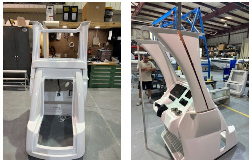
The composition of materials include fiberglass sheets infused with bonding agents. Once the composite has cured, it is removed from the core and further shaped either mechanically or manually. The images below show the RhinoCAM part geometry and the in-process and completed core plug for the Model AirShip 310.
Read the Full Study here.

The RhinoCAM part geometry and basic dimensions.
 The core plug is still in the CMS Athena 5 Axis Machining Center. (Right) The finished core plug, one of several that are ready for layup.")
(Left) The core plug is still in the CMS Athena 5 Axis Machining Center. (Right) The finished core plug, one of several that are ready for layup.
Index 5 Axis Setups
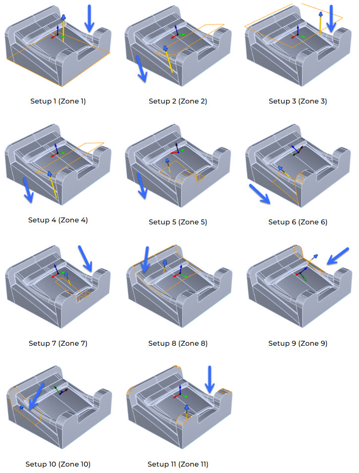
Due to the size and complexity of the part geometry, a total of 11 indexed 5 axis Setups are created, each assigned a specific zone on the part to be machined. Each of these indexed Setups are shown in the Machining Job tree below. Note that the Machining Job is broken into 2 sections in order to fit it on this page.
The Machining Job begins with one 3 Axis Horizontal Roughing operation (Zone 1) followed by a 3 Axis Horizontal Re-Roughing operation (Zone 2). Both zones are identical as far as orientation and containment is concerned. In Zone 2, the Re-Roughing operation calculates the remaining in-process stock left behind after the roughing in Zone 1 is completed.
Zones 3 through 10 all contain 3 Axis Parallel Finishing operations to remove the remaining stock. Zone 11 contains two Parallel Finishing operations and one Between 2 Curves Finishing operation. The posted g-code will contain the multi-axis rotation codes necessary to navigate from one setup to another.

The Machining Job tree is shown above broken into two sections. It shows a total of 11 Setups. The duplicate 3 Axis Parallel Finishing operations are each cut in opposite directions for complete coverage and optimum surface quality.
In the part images below, we show the Setup for each Zone. We have added a blue arrow to indicate the direction and orientation of the cutting tool in that zone. Also, the closed perimeter curves (shown in orange) indicate how the cutting tool is contained within that zone. You can also refer to the Indexed 5 Axis Cut Material Simulations below for the in-process stock after each zone is machined.
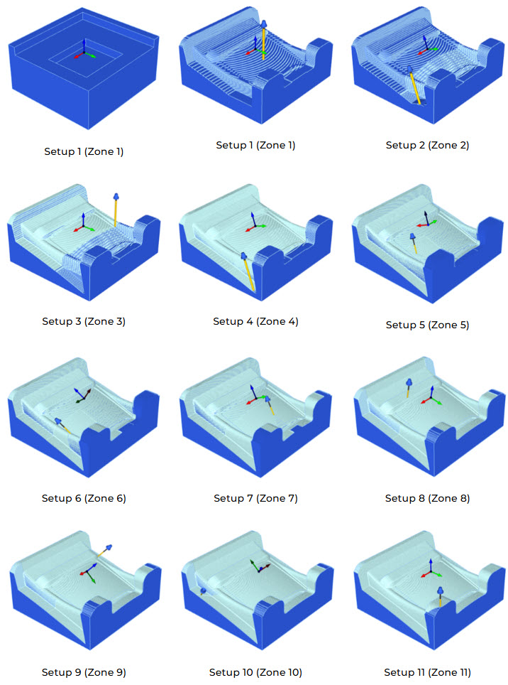
Index 5 Axis Cut Material Simulations
The illustrations below show how the in-process stock material will look after each Setup zone is machined. In the first illustration (top left) you see how the Stock from Selection appears prior to machining. The illustration at Zone 11 below (the last image on the right side) shows how the part will look when all zones are machined.
The Final Product
In the images below we see the completed component and the final assembly for the hard top windshield support ready to be assembled into Airship Rib’s Model AirShip 310 craft.