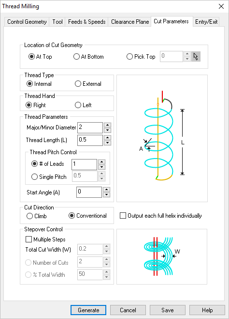
The following Cut Parameters tab allows you to define the roughing parameters for the current 2½ Axis Thread Milling operation. You can set Global Parameters, Cut Geometry parameters, Cut Direction and the Stepover and Stepdown Control via this tab of the operation dialog. The Global Parameters section allows you to set the tolerance value to be used in machining. Refer to each option below.
 Dialog Box: 2½ Axis Thread Milling |
Compensation Compensation can be used to compensate for tool wear. Select AUTO/ON to tell the controller to enable Compensation for this tool. The compensation direction, left or right, is determined by the Cut Direction selected (Climb or Conventional). The actual Compensation offset value is defined on the CNC controller. Cutter Compensation also needs to be enabled in your selected Post Processor. |
For Thread Type, select either Internal or External. Select Internal if your Control Geometry is a circular hole. Select External if your Control Geometry is a circular boss.
|
For Thread Hand, select either Right or Left. This represents the direction of the thread (Right hand or Left hand threads). |
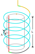
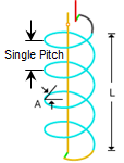
Select from the following options referring to the Cat Parameters tab of the Thread Milling dialog. Major/Minor Diameter For External threads, specify the thread Major Diameter. For Internal threads, specify the thread Minor Diameter. Total Thread Length (L) Enter the total Thread Length (L) of the thread in the field provided.
Start Depth The Start Depth in Thread Milling allows you to control how far from the Control Geometry to start cutting. This allows you to control the amount of relief before the thread begins. Thread Pitch Control For Thread Pitch Control you can choose # of Leads, Single Pitch or Threads per inch (TPI). Then enter either the # of Leads, Single Pitch or Threads per units value in the field provided.
Start Angle (A) For both Internal and External threads, enter thread Start Angle (A) in the field provided.
# of Starts Enter the number of starts for the thread. Single Start Thread: If the # of Starts is one, it means there is only one thread running along the length of the workpiece. In one full rotation of the workpiece or tool, the thread advances by one pitch. Multiple Start Threads: When # of Starts is more than one start (e.g., two starts, three starts), it means that multiple threads begin at different points around the workpiece. For example, with two starts, you would have two threads, each starting 180 degrees apart, and in one full rotation, the tool would advance by two pitches. |
Select Climb (Down Cut) and the tool will be maintained in a downward motion into the stock. 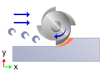 Climb (Down Cut) Select Conventional (Up Cut) and the direction of the tool will be maintained in an upward motion out of the stock. 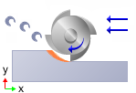 Conventional (Up Cut) Output each full helix individually When available, can check this box to Output each helix individually. This will split each helix into individual full helices of 360 degrees in the posted code. 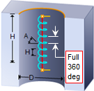 Full 360 deg Helix Output
|
For Stepover Control, check the box for Multiple Steps and then enter the additional stepover control parameters.  Multiple Steps With Multiple Steps checked, enter the Total Cut Width (W). The last stepover will be the final cutting pass for the thread.  Total Cut Width (W) Select Number of Cuts and then enter the number in the field provided. The Total Cut Width will be divided by this number to calculate the Stepover displace.  Number of Cuts |


 One of the basic concepts to understand in any milling operation is