The following Cut Parameters tab allows you to define the cut parameters for the current Roughing operations listed below. You can set Global Parameters, Cut Pattern, Cut Direction and the Stepover Distance via this tab of the operation dialog. The Global Parameters section allows you to set the tolerance value to be used in machining. A uniform thickness or stock that needs to be left around the part can also be specified here. Refer to each option below.
The Global Parameters section allows you to set the tolerance value to be used in machining. Intol and Outol are allowable deviations (tolerances) from the actual part geometry plus the Stock layer (if any). A uniform thickness or stock that needs to be left around the part can be specified here.
Intol / Outol
Inward tolerance - the maximum thickness of material that can be removed from the Stock layer. Outward tolerance is the maximum thickness of material that can remain above the Stock layer.
Tolerances play a vital role in both design engineering and digital manufacturing. In design, the goal is to allow the broadest tolerance range possible while meeting your design specifications. This is because, generally speaking, there is a direct correlation between tighter tolerances and higher manufacturing costs.
Stock
The thickness of the layer that will remain on top of the part after the toolpath is complete. Roughing operations generally leave a thin layer of stock, but for finishing operations this value is zero.
Check this box to offset facing cut patterns based on the control geometry selected. If no control geometry is selected the offset is based on the entire part geometry.
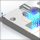
This allows you to define the type of cut pattern that the tool will follow when it is at each Z level. There are six types of patterns that you can choose. Each are shown below. The first two are offset patterns, the third is linear and the last three circular patterns and an emphasis on the new High Speed cut pattern now available in some 2-½, 3 and 4 axis operations.
One of the basic concepts to understand in any milling operation is Cut Direction. It can be characterized by how the flutes of the cutting tool engage the stock material and form the chip that is removed during cutting. In many of MecSoft CAM’s 2½ & 3 Axis toolpath strategies you will see that Cut Direction is defined by selecting one of three options, Climb, Conventional or Mixed. Let’s take a look at the characteristics of each option.
Use the following cut parameters for controlling the cutter during transfer motions.
Cut Lift
During the High Speed cut pattern use this parameter to lift the cutting tool during transfer motions. 0 (Zero) means that the tool will not list. Enter a positive value and the tool will lift this amount in +Z prior to executing a cut transfer motion.
Feedrate Factor
During the High Speed cut pattern use this parameter to control the feed rate when the cutting tool is lifting and plunging before and after each cut transfer motion. The value is a percentage of the Cut Feed (Cf) parameter for this operation (i.e., 50 = 50% of the (Cf) Cut Feed rate).
Automatically detect corners that the tool could not reach between cut level and add a toolpath based on the uncut area detected. Either Linear or Offset cut patterns are used in these areas.
When checked, the system tries, when possible, to keep the cutter in contact with the cut level plane while connecting all areas within a single machining region. Otherwise the cutter will retract and re-engage.
This allows you to define the type of cut pattern in Core/Facing regions that the tool will follow when it is at each Z level. There are two types of patterns that you can choose.
One of the basic concepts to understand in any milling operation is Cut Direction. It can be characterized by how the flutes of the cutting tool engage the stock material and form the chip that is removed during cutting. In many of MecSoft CAM’s 2½ & 3 Axis toolpath strategies you will see that Cut Direction is defined by selecting one of three options, Climb, Conventional or Mixed. Let’s take a look at the characteristics of each option.
Specify the Angle of Cuts (0-360) measured from the X Axis. This additional parameter is available for some operations when a linear cut pattern is used.
Use the following cut parameters for controlling the cutter during transfer motions.
Cut Lift
During the High Speed cut pattern use this parameter to lift the cutting tool during transfer motions. 0 (Zero) means that the tool will not list. Enter a positive value and the tool will lift this amount in +Z prior to executing a cut transfer motion.
Feedrate Factor
During the High Speed cut pattern use this parameter to control the feed rate when the cutting tool is lifting and plunging before and after each cut transfer motion. The value is a percentage of the Cut Feed (Cf) parameter for this operation (i.e., 50 = 50% of the (Cf) Cut Feed rate).
Automatically detect corners that the tool could not reach between cut level and add a toolpath based on the uncut area detected. Either Linear or Offset cut patterns are used in these areas.


")
")

 One of the basic concepts to understand in any milling operation is


