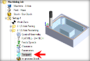
The following Cut Parameters tab allows you to define the cutting parameters for the current 2½ AxisHole Profiling operation. You can set Global, Cut Geometry, Cut Direction and Helix parameters from this tab of the dialog. The Global Parameters section allows you to set the tolerance value to be used in machining. Refer to each option below.
The Global Parameters section allows you to set the tolerance value to be used in machining.
Tolerance (t)
This is the allowable deviation from the actual part geometry plus the Stock layer (if any).
Compensation
Compensation is used to compensate for tool wear. Select AUTO/ON to tell the controller to enable Compensation for this tool. The compensation direction, left or right, is determined by the Cut Direction selected (Climb or Conventional). The actual Compensation offset value is defined on the CNC controller. Cutter Compensation also needs to be enabled in your selected Post Processor.
Tolerances play a vital role in both design engineering and digital manufacturing. In design, the goal is to allow the broadest tolerance range possible while meeting your design specifications. This is because, generally speaking, there is a direct correlation between tighter tolerances and higher manufacturing costs.
The Location of Cut Geometry can be set to At Top (top Z level), At Bottom (bottom Z level) or Pick Top (specifying the Z location) by entering a Z value location or by selecting the pick button and selecting the point on the part.
This uses the Z location of the selected Machining Feature/Region as the top of cut. The generated cuts will start at this Z location and cut down in Z to the specified total cut depth. At Top is typically used when you select the top edge as your machining region.
This uses the Z location of the selected Machining Feature/Region as the bottom of cut. The generated cuts will be above the selected machining region and last cut would be at the Z location of the specified region. At Bottom is typically used when you select a pocket bottom at your machining region.
This allows you to specify the Top of Cut for the selected Machining Feature/Region and is typically used when the selected region is not at top or bottom. The generated cuts will start at this specified Z location and cut down in Z to the specified total cut depth. This would be useful when the selected machining region is at the bottom edge of a fillet or chamfer.
When two or more curves are selected as Machining Features/ Regions, and using Pick Top for Location of Cut Geometry, sets the Top of cut for all regions at the same Z level.
Enter the Hole Depth (H) for the hole profiling operation or select the Pick button and select two points on your part. The depth will be calculated automatically and added to this dialog. The resulting Hole Depth (H) will be measured from the location of the cut geometry selection.
Hole Depth (H)
Determine using 3D Model
When checked, the bottom most level of the part is detected and cut levels will be added to this depth level. Only the Finish Depth needs to be specified. The Rough Depth is automatically determined.
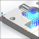
One of the basic concepts to understand in any milling operation is Cut Direction. It can be characterized by how the flutes of the cutting tool engage the stock material and form the chip that is removed during cutting. In many of MecSoft CAM’s 2½ & 3 Axis toolpath strategies you will see that Cut Direction is defined by selecting one of three options, Climb, Conventional or Mixed. Let’s take a look at the characteristics of each option.


")
")
")
")
 One of the basic concepts to understand in any milling operation is
  The following parameters allow you to specify the