This orients the Machine Coordinate System to allow the part to be programmed from other orientations from World Coordinate System (WCS). This is typically used when a part needs to be programmed from more than one side for indexed 5 axis applications.
The Machine Coordinate System (MCS) is displayed as a triad with Blue line representing the Z-axis, Red representing X-axis and Green representing the Y-axis. The WCS is displayed the same way as MCS with XYZ coordinates labeled on top of it.
Allows you to rotate the Machine Coordinate System in X Y Z coordinate axis by any angle specified under Spin Angle. Specify Spin Angle and click the axis to rotate about. Clicking the same coordinate axis button multiple times rotates by the specified angle incrementally. For example if you set the Spin Angle = 90 and click X Axis button 2 times, the MCS is rotated about X coordinate axis by 180 degrees.
If you pick the Reverse Normal button the Z axis of the selected CSYS Setup will reverse, rotating 180 degrees about the positive X axis. Pick Reset to Original to undo any changes and revert the dialog back to the conditions when it was displayed.
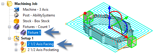
This dialog allows you to assign Fixture definitions to a setup.
Setup, Select Fixtures for Setup tab
Use this tab to select the Fixtures to be applied to this setup. Gouge checking will only apply to the fixtures checked in this dialog. You can use the Select All and Deselect All buttons to assist with your selection.
See Fixture Geometry for information about defining fixture for your part.
Understand that editing a Fixture after it is assigned to a Setup will flag all existing operations in that setup for regeneration.