![]() To create a tool, you either selects the Create/Edit Tool option under the Tools tab in Machining Objects Browser or alternatively by selecting the Create/Edit/Select Tool button under the Tool tab in the machining operation. This brings up the following dialog box that you can utilize to create and edit tool definitions.
To create a tool, you either selects the Create/Edit Tool option under the Tools tab in Machining Objects Browser or alternatively by selecting the Create/Edit/Select Tool button under the Tool tab in the machining operation. This brings up the following dialog box that you can utilize to create and edit tool definitions.
![]() INCH & METRIC TOOLS: If you use both inch and metric tools, you will need to create two separate tool libraries. That is because the tool dimensions adopt the current UNITS setting of the host CAD system.
INCH & METRIC TOOLS: If you use both inch and metric tools, you will need to create two separate tool libraries. That is because the tool dimensions adopt the current UNITS setting of the host CAD system.
 Dialog Box: Create/Select Tools |
The tool icon bar on the top of the dialog displays the all various types of tools available in MILL module. Different tool types can be defined by selecting the desired icon in the dialog box. Note: The actual tools that you will see listed in this toolbar will depend on what module and what configuration you are currently running.  Create Tools Toolbar |
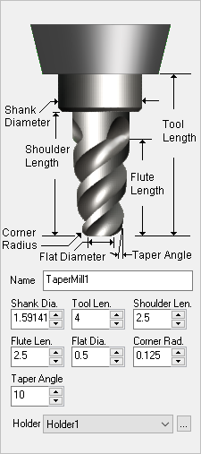
The dialog box shows the tool name of the current selection if there is one selected in the list-box under Tools in Session. If there is no selection then the tool name will be the name used for a new tool definition. The list box itself lists all of the tools of the corresponding type.  Tools in Session Tool Representation The icon representation of the tool shows where the dimensions listed below are measured from. Please refer to this image when entering your tool dimensions. Name Enter a unique name for the tool. Tools are defined by their Name. You cannot have more than one tool with the same name. Dimensions Enter the tool dimensions using the fields provided. It is best to have the Tool Dia. and the Shank Dia. the same dimension even if your tool is different. Shoulder Len. must be larger than the Flute Len. Holder If you have Tool Holders defined, select the holder that you want assigned to this tool. To create and manage Holders select the ... button to display the Create/Select Holder dialog. |
The geometry definition of the tool contains edit boxes for the diameter, corner radius, taper angle, flute length and the tool length. These definitions are standard APT parameters for the tool definition. The flute length denotes the cutting length while the tool length denotes the total length of the tool to the tool holder. |
Save As New Tool Saves a new tool and lists under Tools in Session. If a tool of same name already exist under Tools in Session, Save as New tool button will be grayed out. Save Edits to Tool Saves edits or changes made to tool parameters.
Delete Tool Deletes the selected tool. A tool will not be deleted a tool if is being used in a machining operation. |
As the tool geometry is defined, a preview of the tool is shown in the graphics window.  Tool Preview |
The Properties tab to the right side of the tool preview allows you to set the Tool Material, the Cut Material Color (for that Tool), Number of Flutes in the tool, Tool Number, Adjust Register, Cutter Compensation Register, Axial Offset, Coolant Type. The Number of Flutes is used in Feeds & Speeds calculations. The tool number is used when post processing toolpaths.
 The Properties tab  Cut Material by Color Material This sets the material definition for the active tool. This material is also used in the Load from File option, also referred to as the Feeds & Speeds Calculator. Cut Material Color You can set the cut material simulation color for this tool. To view this color during simulations, set the Simulation Display State to Tool. This control is located to the right of the toolbar at the bottom of the Simulate tab.
Number of Flutes This defines the total number of flutes for the active tool. Adjust Register This is used to set the Tool Length Offset (an integer). Generally this is set the same as Tool Number. The posted code would output H<#> and the # corresponds to the offset value in the controller’s tool table. Note the post processor needs to be configured to output the Adjust Register. For example N20 T1 M6 N30 G43 H1 Z0.25 Where H1 points to the controllers tool table for tool length compensation. Cutcom Register This is used to set the Tool Diameter Offset (an integer) for cutter compensation / tool wear compensation at the controller. Generally this is set the same as Tool Number. The posted code would output D<#> and the # corresponds to the offset value in the controller’s tool table. For example N30 G41 X 2.0 Y 1.0 D1 Where D1 points to the controllers tool table for diameter compensation. Note the post processor needs to be configured to output the Cutter Compensation. Refer to Cutter Compensation for detailed description. Axial Offset This parameter offsets the Z value in the posted g-code by the specified value. This can be set to a positive or negative value and can be an integer or decimal. Use of Dove Tail, Fillet Mill, Lollipop cutter and User Defined tools are limited to 2½ Axis Profiling and Engraving operations. Coolant Here you can override the Coolant that is specified by the Tool. Coolant can be set to Flood, Mist, Through or Air. Coolant codes are defined in the post processor generator under Misc tab. Coolant Off is also supported as a variable that can be added where needed using the post-processor generator.  Coolant selections available Comments Outputs specified comments in the posted g-code before a tool change.  Tool Comments Adding $ as prefix would skip the comment start and end characters in the posted output file.  Tool Comments The posted code would include the comments in the output as shown below.
(END MILL – 0.5 INCH) M00 |
The Feeds & Speeds tab located next to Properties tab allows you to set feeds and speeds for each tool. Refer to the Feeds and Speeds section for additional information. Cut Depth
 The Feeds & Speeds tab |
Taper Angle is set for VeeMill, ChamferMill and TaperMill. This angle is the included angle. For a 60 degree taper tool, the Taper Angle is set as 30.  Taper Angle |
Flat Diameter is set for ChamferMill and TaperMill. When Flat diameter is set =0, the tip converges to a point. To define a ball mill with taper, set Flat diameter = 0 and Corner Radius = tool radius. In the example shown below, Flat Dia = 0 and Corner Radius = 0.25. This creates a 0.5” ball mill with a 10 degree taper.
|