In Continuous 5-Axis machining, the spindle’s constantly changing orientation necessitates specific mechanisms in the 3D model and toolpath method to calculate the Z-axis orientation at every cut point. Two types of control geometry are employed: Drive Surfaces and Check Surfaces, each described and illustrated below.
") 3D Model Showing Drive Surfaces (in Green) |
 Cross-section of the 3D Model illustrating the Spindle orientation relative to the Drive Surface |
Drive Surface Control Geometry in 5 Axis
In Continuous 5-Axis toolpaths, the Drive Surface governs spindle orientation. At each cut point, a perpendicular (normal) vector is calculated from the Drive Surface, setting the cutting tool’s axis. The quantity of cut points is controlled by the Tolerance parameter in the 5-Axis Surface Normal dialog. The image below illustrates the Drive Surface and spindle orientation for Continuous 5-Axis Surface Normal finishing.

The role of Drive Surfaces in Continuous 5 Axis Surface Normal finishing
Check Surface Control Geometry in 5 Axis
In Continuous 5-Axis toolpaths, Check Surfaces specify areas the cutter must not contact, encompassing surfaces or meshes, commonly termed 5-Axis Gouge Checking. In our 3D part model, the Drive Surface is fully enclosed within the 3D mesh model’s volume, which is suitable since it serves only to guide spindle orientation, not for machining. By defining the 3D mesh model as the Check Surface, the cutting tool is prevented from breaching it. The synergy between Drive and Check Surfaces allows RhinoCAM (and VisualCADCAM) to produce continuous 5-Axis toolpaths for mesh models.
You can refer to the illustrations below.
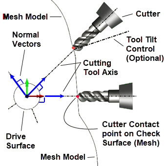
Above we see the interplay of the Drive Surface and the Check Surface (Mesh) for calculating a Continuous 5 Axis toolpath on a 3D mesh model.
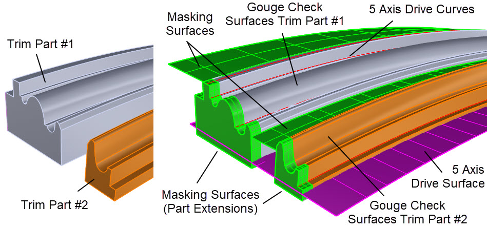
Above we see the interplay of Drive Curves, Drive Surface and Check Surface (3D Part Surfaces) for calculating a Continuous 5 Axis toolpath on a 3D NURBs model.