The following Cut Parameters tab allows you to define the cut parameters for the current 2½ Axis Re-Machining operation. You can set Global Parameters, Reference Operation Parameters and the Stepover Distance via this tab. The Global Parameters section allows you to set the tolerance value to be used in machining. A uniform thickness or stock that needs to be left around the part can also be specified here. Refer to each option below.
The Global Parameters section allows you to set the tolerance value to be used in machining. A uniform thickness or stock that needs to be left around the part can be specified here.
Tolerance
This is the allowable deviation from the actual part geometry plus the Stock allowance (if any). In 2 Axis methods, this Tolerance is applied to XY motions only.
Tolerances play a vital role in both design engineering and digital manufacturing. In design, the goal is to allow the broadest tolerance range possible while meeting your design specifications. This is because, generally speaking, there is a direct correlation between tighter tolerances and higher manufacturing costs.
This is the thickness of the layer that will remain on top of the part after the toolpath is complete. Roughing operations generally leave a thin layer of stock. For finishing operations this value is zero.
Stock
Compensation
Compensation can be used to compensate for tool wear. Select AUTO/ON to tell the controller to enable Compensation for this tool. The compensation direction, left or right, is determined by the Cut Direction selected (Climb or Conventional). The actual Compensation offset value is defined on the CNC controller. Cutter Compensation also needs to be enabled in your selected Post Processor.
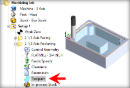
The Reference Operation needs to be determined (select from the following) along with the Reference Tool Diameter (D) & Taper Angle. Once the uncut areas are determined, they will be cut using the a Facing toolpath.
Right / Left
This can be set for both open and closed curves. For example, for a clockwise arc/circle, the right side would be inside the arc/circle and the left side would be outside the arc/circle.
Cut Start Side – Right
Cut Start Side – Left
Use Outside or Inside for Closed Curves
For closed curves, you can set the Cut Start Side by selecting Use Outside or Inside for Closed Curves and select Outside or Inside.
Determine using the 3D model
If a 3D model is being used, check this box to automatically determine the Start Side. This option may not be available for all 2½ Axis operations.
Note: This feature is not available in Xpress configuration.
Control Geometry should lie on the 3D Model: If you check the box to Determine using 3D model, make sure the Control Geometry you have selected lies completely On the 3D model or unexpected results my occur.
Select Climb (Down Cut) and the tool will be maintained in a downward motion into the stock.
Climb (Down Cut)
Conventional (Up Cut)
Select Conventional (Up Cut) and the direction of the tool will be maintained in an upward motion out of the stock.
Conventional (Up Cut)
Mixed
Select Mixed and the direction of cutting is alternated between each parallel plane. This is a mixture of both Climb and Conventional cutting of the stock.
One of the basic concepts to understand in any milling operation is Cut Direction. It can be characterized by how the flutes of the cutting tool engage the stock material and form the chip that is removed during cutting. In many of MecSoft CAM’s 2½ & 3 Axis toolpath strategies you will see that Cut Direction is defined by selecting one of three options, Climb, Conventional or Mixed. Let’s take a look at the characteristics of each option.
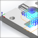
When Mixed is selected, zigzag motions are applied between step downs to eliminate tool retracts between z levels. If Climb or Conventional is selected, retract between z levels are applied. Refer to the images below:


")
")

 One of the basic concepts to understand in any milling operation is
