To create a tool, you either selects the Create/Edit Tool option under the Tools tab in Machining Objects Browser or alternatively by selecting the Create/Edit/Select Tool button under the Tool tab in the machining operation. This brings up the following dialog box that you can utilize to create and edit tool definitions.
INCH & METRIC TOOLS: If you use both inch and metric tools, you will need to create two separate tool libraries. That is because the tool dimensions adopt the current UNITS setting of the host CAD system.
The tool icon bar on the top of the dialog displays the all various types of tools available in MILL module. Different tool types can be defined by selecting the desired icon in the dialog box.
Note: The actual tools that you will see listed in this toolbar will depend on what module and what configuration you are currently running.
The dialog box shows the tool name of the current selection if there is one selected in the list-box under Tools in Session. If there is no selection then the tool name will be the name used for a new tool definition. The list box itself lists all of the tools of the corresponding type.
Tools in Session
Tool Representation
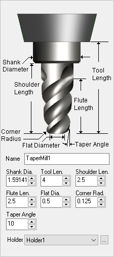
The icon representation of the tool shows where the dimensions listed below are measured from. Please refer to this image when entering your tool dimensions.
Name
Enter a unique name for the tool. Tools are defined by their Name. You cannot have more than one tool with the same name.
Dimensions
Enter the tool dimensions using the fields provided. It is best to have the Tool Dia. and the Shank Dia. the same dimension even if your tool is different. Shoulder Len. must be larger than the Flute Len.
Holder
If you have Tool Holders defined, select the holder that you want assigned to this tool. To create and manage Holders select the ... button to display the Create/Select Holder dialog.
The geometry definition of the tool contains edit boxes for the diameter, corner radius, taper angle, flute length and the tool length. These definitions are standard APT parameters for the tool definition. The flute length denotes the cutting length while the tool length denotes the total length of the tool to the tool holder.
Saves a new tool and lists under Tools inSession. If a tool of same name already exist under Tools in Session, Save as New tool button will be grayed out.
Save Edits to Tool
Saves edits or changes made to tool parameters.
When you Save Edits to Tool, each Mop in the Machining Job tree that uses the Load from Tool option, will be updated with the new feeds/speeds for that tool automatically.
Delete Tool
Deletes the selected tool. A tool will not be deleted a tool if is being used in a machining operation.
The Properties tab to the right side of the tool preview allows you to set the ToolMaterial, the Cut Material Color (for that Tool), Number of Flutes in the tool, Tool Number, Adjust Register, CutterCompensation Register, Axial Offset, Coolant Type. The Number of Flutes is used in Feeds & Speeds calculations. The tool number is used when post processing toolpaths.
Material
This sets the material definition for the active tool. This material is also used in the Load from File option, also referred to as the Feeds & Speeds Calculator.
Cut Material Color
You can set the cut material simulation color for this tool. To view this color during simulations, set the Simulation Display State to Tool. This control is located to the right of the toolbar at the bottom of the Simulate tab.
Number of Flutes
This defines the total number of flutes for the active tool.
Adjust Register
This is used to set the Tool Length Offset (an integer). Generally this is set the same as Tool Number. See Adjust Register for more information.
Cutcom Register
This is used to set the Tool Diameter Offset (an integer) for cutter compensation / tool wear compensation at the controller. Generally this is set the same as Tool Number. See Cutcom Register for more information.
Axial Offset
This parameter offsets the Z value in the posted g-code by the specified value. This can be set to a positive or negative value and can be an integer or decimal. See Axial Offset for more information.
Coolant
Here you can override the Coolant that is specified by the Tool. Coolant can be set to Flood, Mist, Through or Air Through. Coolant codes are defined in the post processor generator under Misc tab. Coolant Off is also supported as a variable that can be added where needed using the post-processor generator.
Coolant selections available
Comments
Outputs specified comments in the posted g-code before a tool change. See Comments for more information.
The Feeds & Speeds tab located next to Properties tab allows you to set feeds and speeds for each tool.
Refer to the Feeds and Speeds section for additional information.
Spindle Parameters
Speed
This is the rotational Speed (S) of the milling spindle expressed in RPM.
Direction
This determines the direction of spindle rotation and can be set to Clockwise (CW) or Counter Clockwise (CCW).
Feed Rates (in/mm)
Plunge
This is the rate is the feed before the tool starts to engage in material. This is always vertical.
Approach
This is the Approach (Af) feedrate (in Units/Min) used to prepare the cutter just before it starts to Engage into material for cutting. Approach motions are dependent on the method of machining.
Engage
This is the feedrate used when the tool is performing an engage move. TURN Module sets this value to be 75% of the cutting speed.
Cut
This is the feedrate used when the tool is cutting material.
Retract
This is the feedrate used when the tool is performing a retract move away from material. TURN Module sets this also to 75% of the cutting speed.
Departure
This is the Departure (Df) feedrate (in Units/Min) used when the tool is Departing from the material.
Transfer
This is the Transfer (Tf) feedrate (in Units/Min) used for Transfer motions. If you select Use Rapid the posted G-Code will output a rapid motion (G0) with no feed rate. Note: For more accurate machining time estimates, use the Set option and enter the feed rate to use.
Feed Rate Reduction Factors
Plunge Between Levels
This is a percentage of the Cut (Cf) feedrate to use when the tool is plunging between Z levels.
First XY Pass
This is a percentage of the Cut (Cf) feedrate to use on the first XY cut motion when the toolpath uses the full width of the cutter.
Bottom Z Level
Here you can specify the percentage of the Cut (Cf)FeedRate to use for the Bottom Z Level. This could be the bottom of a pocket operation or the bottom of a profile operation. This applies to any toolpath with levels.
Cut Depth
You can set the Cut Depth specific for each tool you create. If you set this value here, you will see a Depth From Tool icon next to the Rough Depth/Cut parameter in the Cut Levels tab of each operation where it applies. Selecting the icon will use this value for Rough Depth/Cut. If Cut Depth is left at 0 in this dialog, the icon will not appear in the Cut Levels tab.
Load from File
This button allows you to load Feeds & Speed values from a saved Feeds & Speeds Table file.